Clutch mechanism

a technology of clutch mechanism and hub, which is applied in the direction of friction clutch, non-mechanical actuated clutch, clutch, etc., can solve the problems of insufficient reduction of operating noise, inability to limit the vibration of the armature immediately after the collision, and the above conventional technology of jp-um-a-62-167936 cannot be applied to the plate spring hub clutch mechanism

Active Publication Date: 2011-06-02
DENSO CORP
View PDF7 Cites 14 Cited by
  • Summary
  • Abstract
  • Description
  • Claims
  • Application Information

AI Technical Summary

Problems solved by technology

However, in the above conventional technology of JP-A-2003-247565, the impact at the time of collision between the armature and the rotor is only mitigated, and vibration of the armature immediately after the collision cannot be limited.
Therefore, reduction of the operating noise is insufficient.
Thus, the configuration of the above conventional technology of JP-UM-A-62-167936 cannot be simply applied to the plate spring hub type clutch mechanism.

Method used


Image

  • Clutch mechanism
  • Clutch mechanism
  • Clutch mechanism

Examples


first embodiment

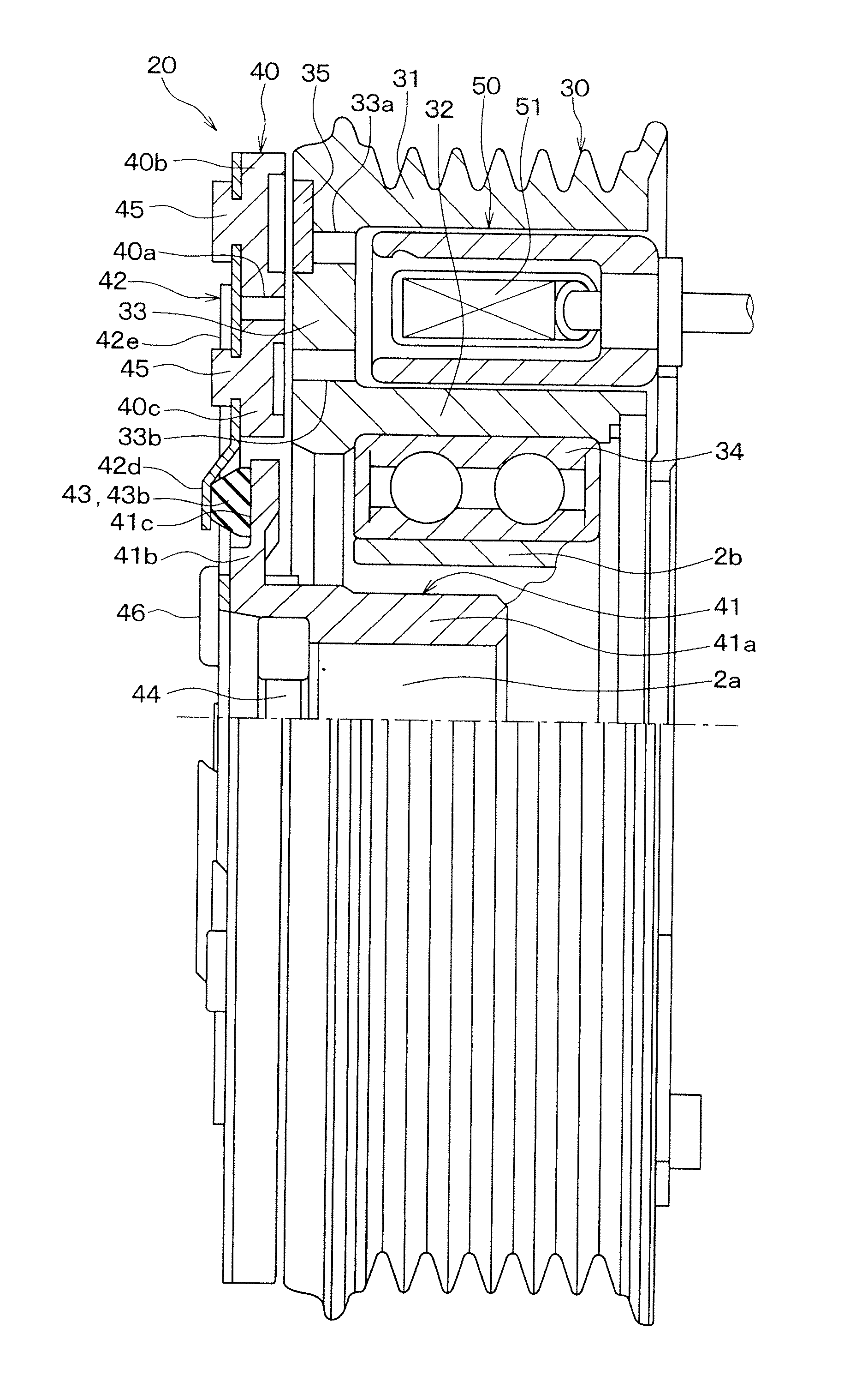
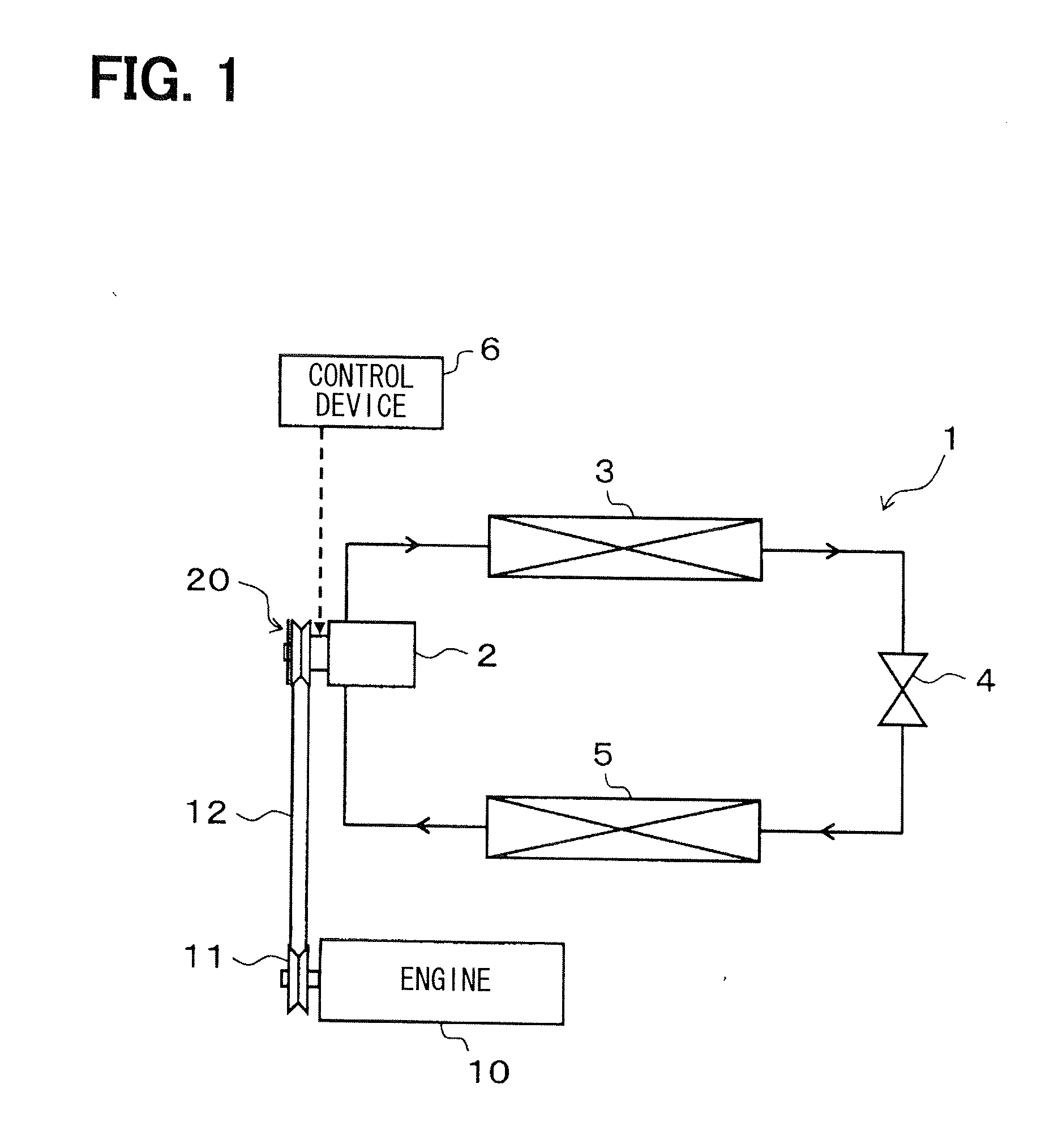
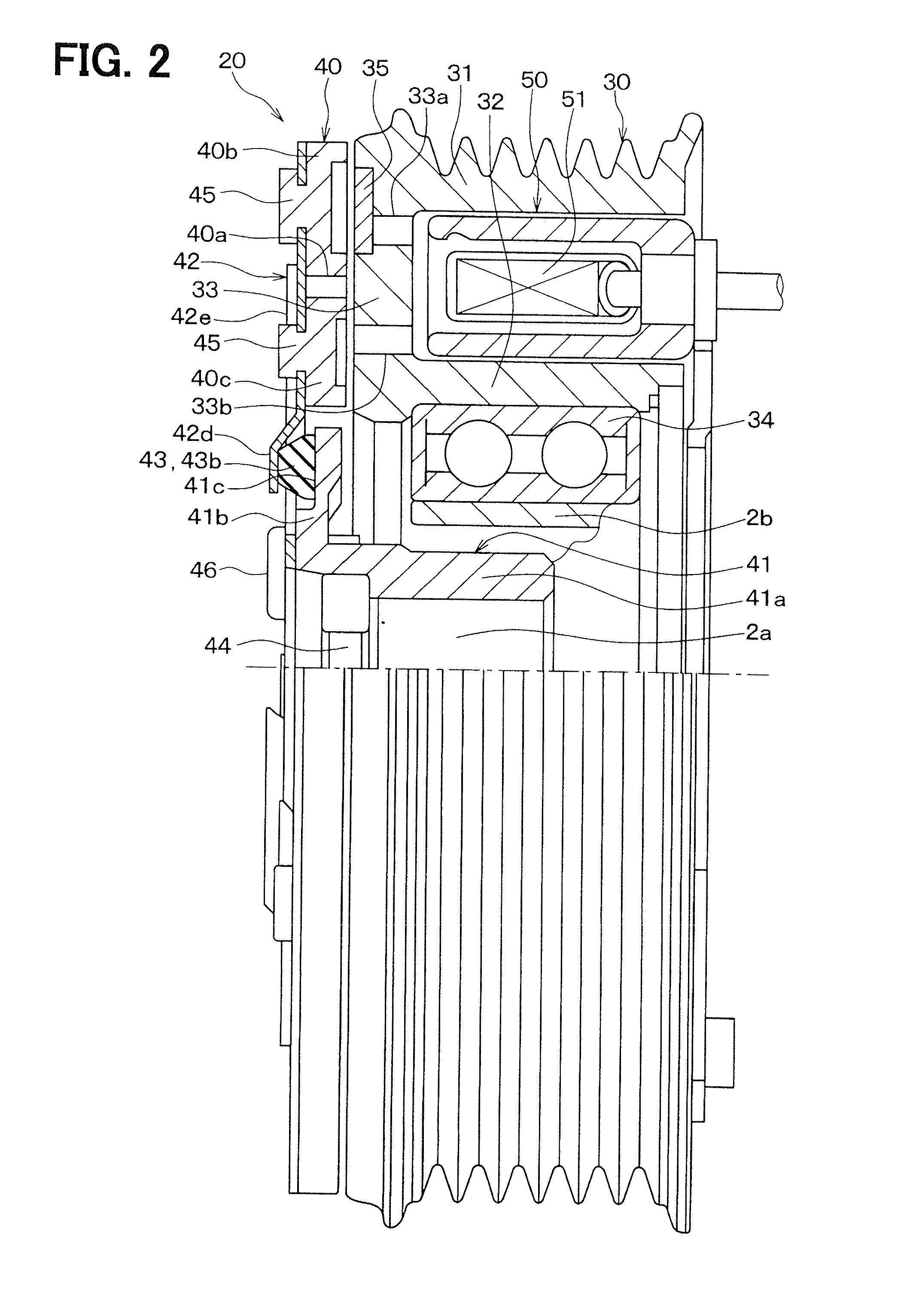
[0042]A first embodiment of the invention will be described with reference to FIGS. 1 to 6B. FIG. 1 is a diagram illustrating an entire configuration of a refrigeration cycle system 1 of an air conditioner for a vehicle, to which a clutch mechanism of the present embodiment is applied. The refrigeration cycle system 1 is a refrigerant circulation circuit that includes a compressor 2, a radiator 3, an expansion valve 4 and an evaporator 5, which are connected in series.

[0043]The compressor 2 suctions and compresses refrigerant. The radiator 3 makes the refrigerant discharged from the compressor 2 release heat. The expansion valve 4 decompresses and expands the refrigerant flowing out from the radiator 3. The evaporator 5 evaporates the refrigerant decompressed by the expansion valve 4 to produce an endothermic effect.

[0044]The compressor 2 obtains rotational driving force from an engine 10, which is a drive source that outputs driving force for vehicle traveling, to rotate a compress...

second embodiment

[0104]In the above first embodiment, the damper 43 is formed separately from the armature 40. In a second embodiment of the invention, as illustrated in FIGS. 7A and 7B, a damper 43 is formed integrally with the armature 40.

[0105]As a method for forming the damper 43 integrally with the armature 40, insert molding, for example, is employed. Because of the formation of the damper 43 integrally with the armature 40, the connecting part 43d of the damper 43 in the first embodiment is partly omitted. Specifically, a connecting part 43d connecting a flexure applying part 43a and a vibration reduction part 43c is no longer used.

[0106]Because both the flexure applying part 43a and the vibration reduction part 43c overlap with the armature 40, the connecting part 43d connecting the flexure applying part 43a and the vibration reduction part 43c does not need to be formed in the present embodiment. On the other hand, an impact mitigation part 43b which overlaps with an inner hub 41 is dispose...

third embodiment

[0110]In the above second embodiment, the damper 43 is formed integrally with the armature 40. In a third embodiment of the invention, as illustrated in FIG. 9A to 9D, a damper 43 is formed integrally with a plate spring 42.

[0111]As a method for forming the damper 43 integrally with the armature 40, insert molding, for example, is employed. In the example of FIGS. 9A to 9D, in order to facilitate forming of the damper 43, an impact mitigation part 43b and a vibration reduction part 43c of the damper 43 are formed in an elliptical integrated shape, and a compression part 42d and a pressing part 42e of the plate spring 42 are also formed in an elliptical integrated shape. As a result, stepped portions 42g, 42h of the plate spring 42 are formed in an arc-shaped integrated shape.

[0112]As illustrated in FIG. 9D, a retaining structure using a gate at the time of forming of the damper 43 is formed at an overlapping portion between the damper 43 and the plate spring 42. More specifically, w...


PUM


Abstract

A clutch mechanism includes a pulley, an armature, an electromagnet, a plate spring, and a damper. The armature is joined to the pulley in a direction of a rotation axis. The electromagnet generates attracting magnetic force, which attracts the armature in a joining direction. The plate spring generates resilient force, which urges the armature in an opposite direction from the joining direction. The damper includes an impact mitigation part mitigating an impact when the armature collides with the pulley. The pulley, the armature, the damper, and the plate spring are arranged in this order in the direction of the rotation axis. The damper includes a contact portion in contact with part of the armature in the direction of the rotation axis. The plate spring includes a pressing part pressing the contact portion on the armature both at time of joining and at time of unjoining between the armature and the pulley.

Description

CROSS REFERENCE TO RELATED APPLICATION[0001]This application is based on and incorporates herein by reference Japanese Patent Application No. 2009-271475 filed on Nov. 30, 2009.BACKGROUND OF THE INVENTION[0002]1. Field of the Invention[0003]The present invention relates to a clutch mechanism that turns on and off transmission of rotative power.[0004]2. Description of Related Art[0005]Conventionally, as a clutch mechanism of this kind, a plate spring hub type clutch mechanism that uses a plate spring for turning on and off of transmission of rotational driving force from a rotor, which is a driving side rotating body, to an armature, which is a driven side rotating body, is known (e.g., JP-A-2003-247565 corresponding to US2003 / 0159901A1).[0006]In the plate spring hub type clutch mechanism, upon energization of an electromagnet, the armature is attracted and coupled to the rotor-side, so that the rotational driving force is transmitted, and when the energization of the electromagnet i...

Claims


Application Information

Patent Timeline
Patent Type & Authority Applications(United States)
IPC IPC(8): F16D13/40F16D27/00
CPCF16D2027/007F16D27/112
Inventor SAKURABA, SHIGEYOSHITABUCHI, YASUO
Owner DENSO CORP
Why Eureka
Try Eureka