Clutch mechanism
a technology of clutch mechanism and hub, which is applied in the direction of interlocking clutches, couplings, friction linings, etc., can solve the problems of insufficient reduction of operating noise, inability to limit the vibration of the armature immediately after the collision, and the above conventional technology of jp-um-a-62-167936 cannot be applied to the plate spring hub clutch mechanism
- Summary
- Abstract
- Description
- Claims
- Application Information
AI Technical Summary
Benefits of technology
Problems solved by technology
Method used
Image
Examples
first embodiment
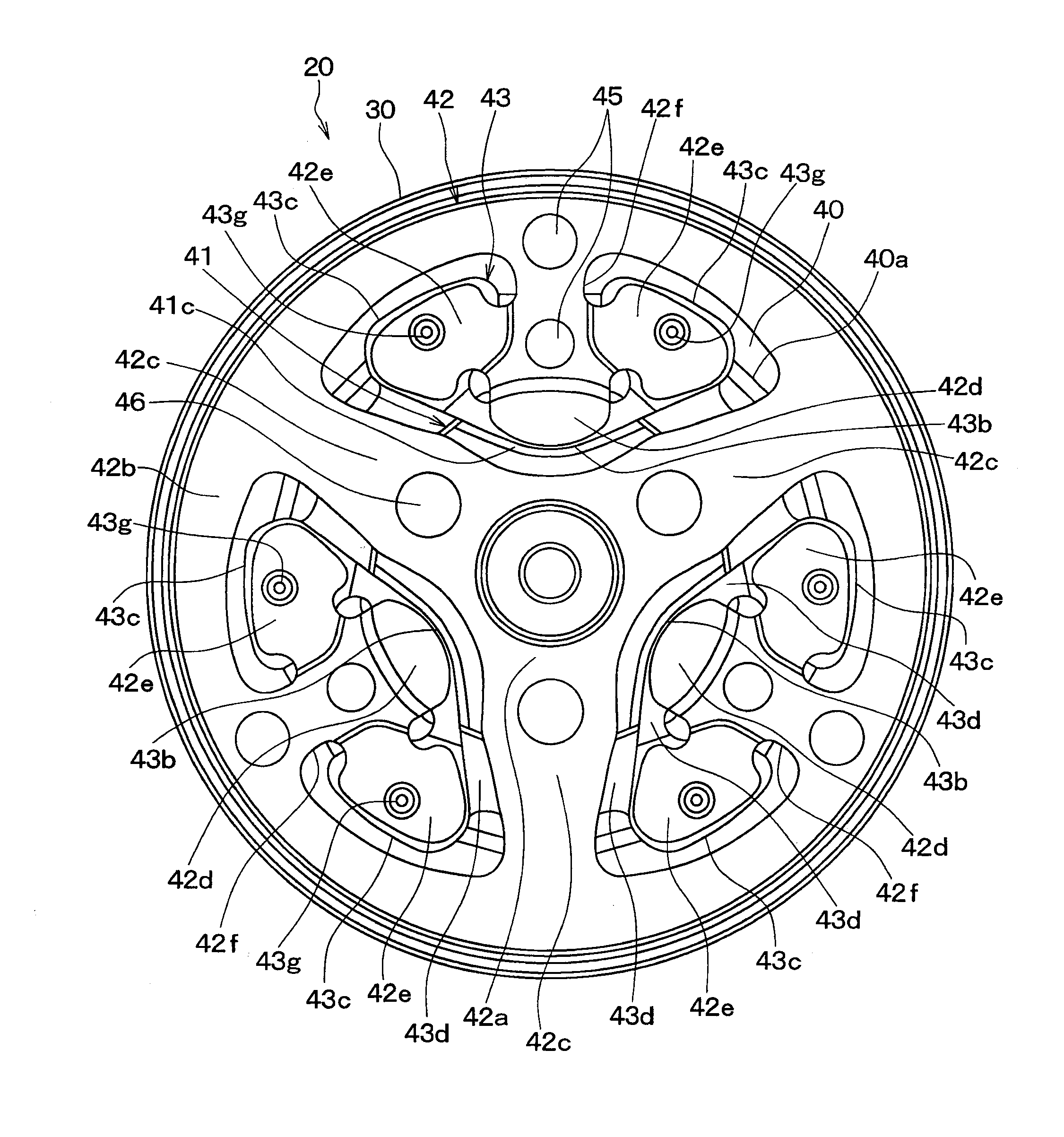
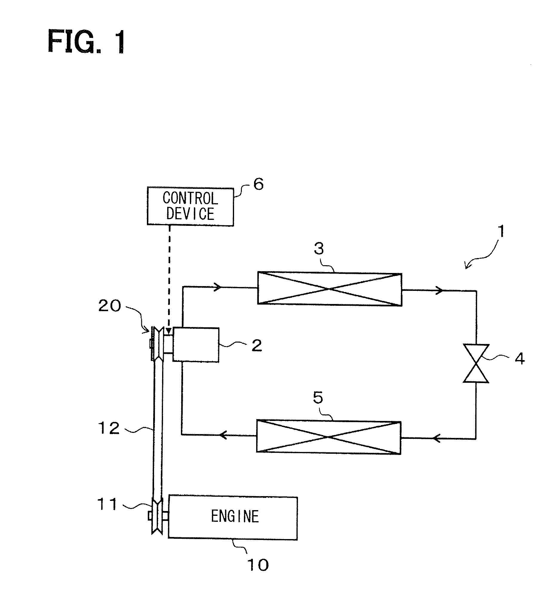
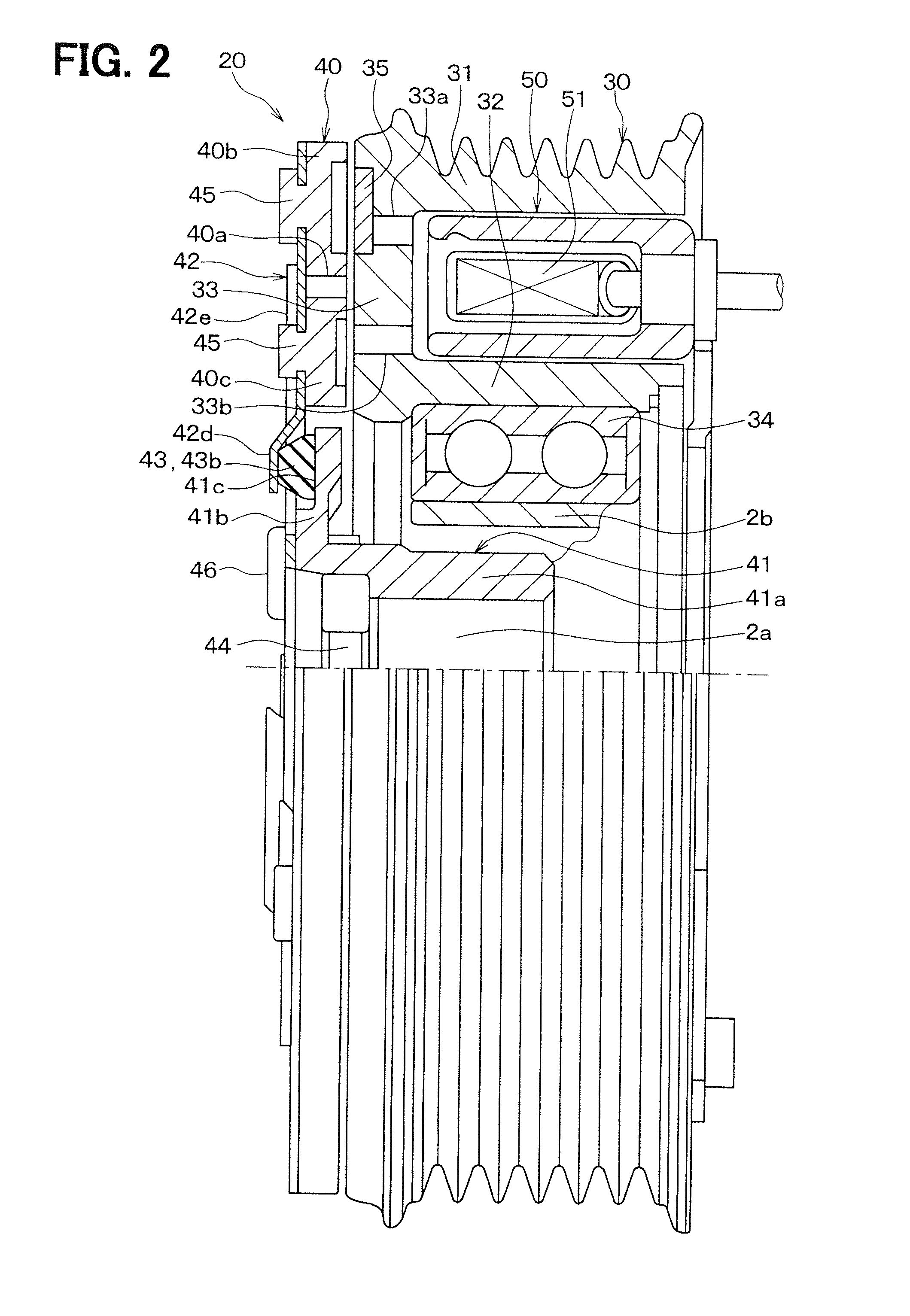
[0042]A first embodiment of the invention will be described with reference to FIGS. 1 to 6B. FIG. 1 is a diagram illustrating an entire configuration of a refrigeration cycle system 1 of an air conditioner for a vehicle, to which a clutch mechanism of the present embodiment is applied. The refrigeration cycle system 1 is a refrigerant circulation circuit that includes a compressor 2, a radiator 3, an expansion valve 4 and an evaporator 5, which are connected in series.
[0043]The compressor 2 suctions and compresses refrigerant. The radiator 3 makes the refrigerant discharged from the compressor 2 release heat. The expansion valve 4 decompresses and expands the refrigerant flowing out from the radiator 3. The evaporator 5 evaporates the refrigerant decompressed by the expansion valve 4 to produce an endothermic effect.
[0044]The compressor 2 obtains rotational driving force from an engine 10, which is a drive source that outputs driving force for vehicle traveling, to rotate a compress...
second embodiment
[0104]In the above first embodiment, the damper 43 is formed separately from the armature 40. In a second embodiment of the invention, as illustrated in FIGS. 7A and 7B, a damper 43 is formed integrally with the armature 40.
[0105]As a method for forming the damper 43 integrally with the armature 40, insert molding, for example, is employed. Because of the formation of the damper 43 integrally with the armature 40, the connecting part 43d of the damper 43 in the first embodiment is partly omitted. Specifically, a connecting part 43d connecting a flexure applying part 43a and a vibration reduction part 43c is no longer used.
[0106]Because both the flexure applying part 43a and the vibration reduction part 43c overlap with the armature 40, the connecting part 43d connecting the flexure applying part 43a and the vibration reduction part 43c does not need to be formed in the present embodiment. On the other hand, an impact mitigation part 43b which overlaps with an inner hub 41 is dispose...
third embodiment
[0110]In the above second embodiment, the damper 43 is formed integrally with the armature 40. In a third embodiment of the invention, as illustrated in FIG. 9A to 9D, a damper 43 is formed integrally with a plate spring 42.
[0111]As a method for forming the damper 43 integrally with the armature 40, insert molding, for example, is employed. In the example of FIGS. 9A to 9D, in order to facilitate forming of the damper 43, an impact mitigation part 43b and a vibration reduction part 43c of the damper 43 are formed in an elliptical integrated shape, and a compression part 42d and a pressing part 42e of the plate spring 42 are also formed in an elliptical integrated shape. As a result, stepped portions 42g, 42h of the plate spring 42 are formed in an arc-shaped integrated shape.
[0112]As illustrated in FIG. 9D, a retaining structure using a gate at the time of forming of the damper 43 is formed at an overlapping portion between the damper 43 and the plate spring 42. More specifically, w...
PUM
 Abstract
Description
Claims
Application Information
 - R&D
- Intellectual Property
- Life Sciences
- Materials
- Tech Scout
- Unparalleled Data Quality
- Higher Quality Content
- 60% Fewer Hallucinations
Browse by: Latest US Patents, China's latest patents, Technical Efficacy Thesaurus, Application Domain, Technology Topic, Popular Technical Reports.
© 2025 PatSnap. All rights reserved.Legal|Privacy policy|Modern Slavery Act Transparency Statement|Sitemap|About US| Contact US: help@patsnap.com


