Camera calibration system and coordinate data generation system and method thereof

a calibration system and camera technology, applied in the field of camera calibration methods and coordinate data generation methods, can solve the problems of difficult to find feature points, difficult for the operator to determine in the surveillance image which camera the monitored person will appear, and inability to immediately determine the position and movement of the monitored person, etc., to achieve the effect of quick generation and calibration of the camera

Inactive Publication Date: 2011-06-02
IND TECH RES INST
View PDF8 Cites 34 Cited by
  • Summary
  • Abstract
  • Description
  • Claims
  • Application Information

AI Technical Summary

Benefits of technology

[0018]As described above, in the disclosure, a coordinate transform matrix between the image coordinate data of a camera and the map coordinate data of a real scene can be quickly generated so as to calibrate the camera.

Problems solved by technology

However, since the direction and size of the surveillance image are restricted by the deployed position of the camera, the operator cannot instantly determine the position and movement of the monitored person.
Especially when the monitored person moves out of the monitored area of a single camera and is about to cross over the monitored areas of different cameras, it is difficult for the operator to determine in the surveillance image of which camera the monitored person will appear again.
However, in this technique, it is not easy to find the feature points that are easy to be identified on both the image plane and the ground plane.
As to a large surveillance system, there may be hundreds of surveillance cameras and accordingly it may be very time-consuming and labor-consuming to calibrate the cameras in such a large-scaled system.

Method used


Image

  • Camera calibration system and coordinate data generation system and method thereof
  • Camera calibration system and coordinate data generation system and method thereof
  • Camera calibration system and coordinate data generation system and method thereof

Examples


first exemplary embodiment

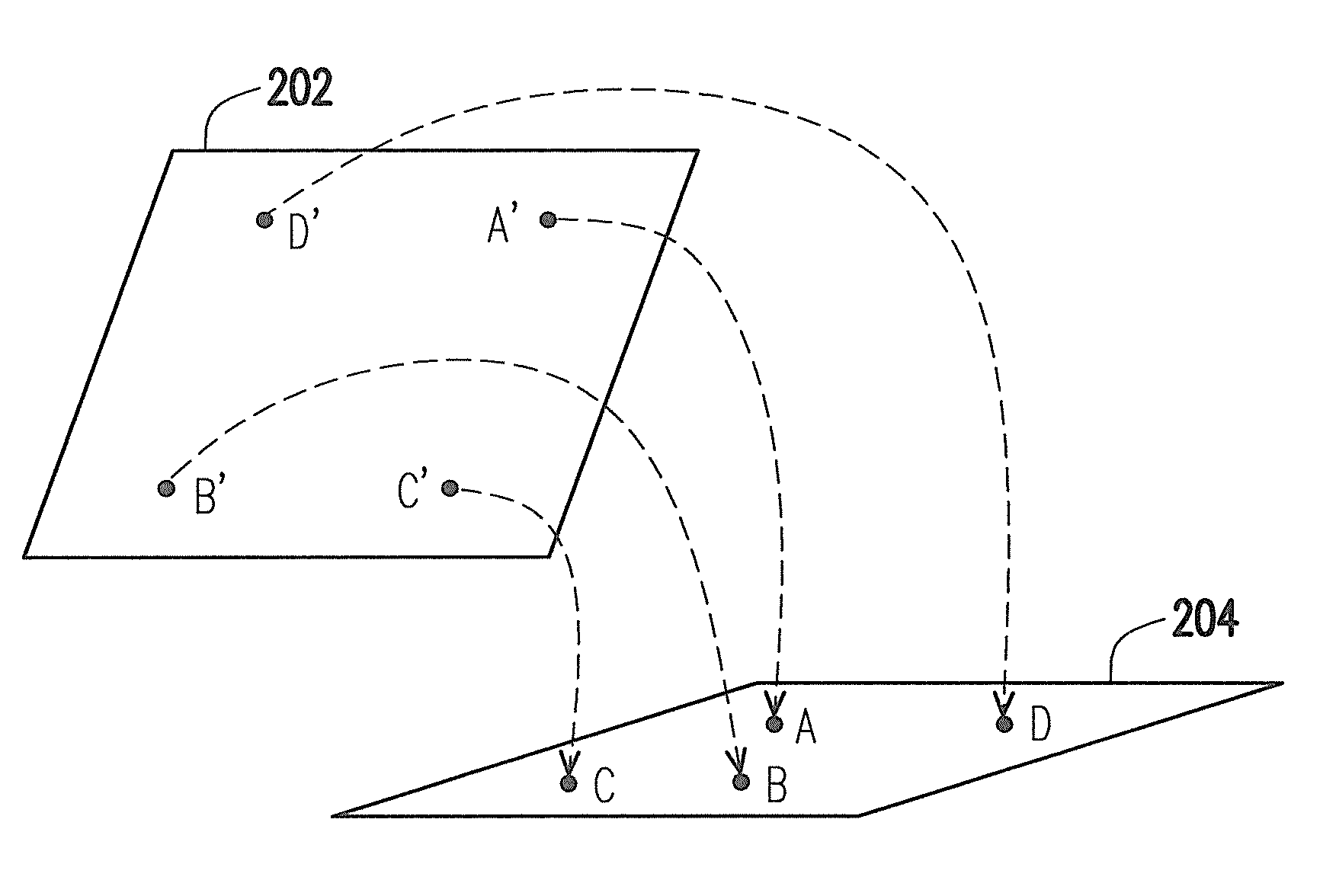
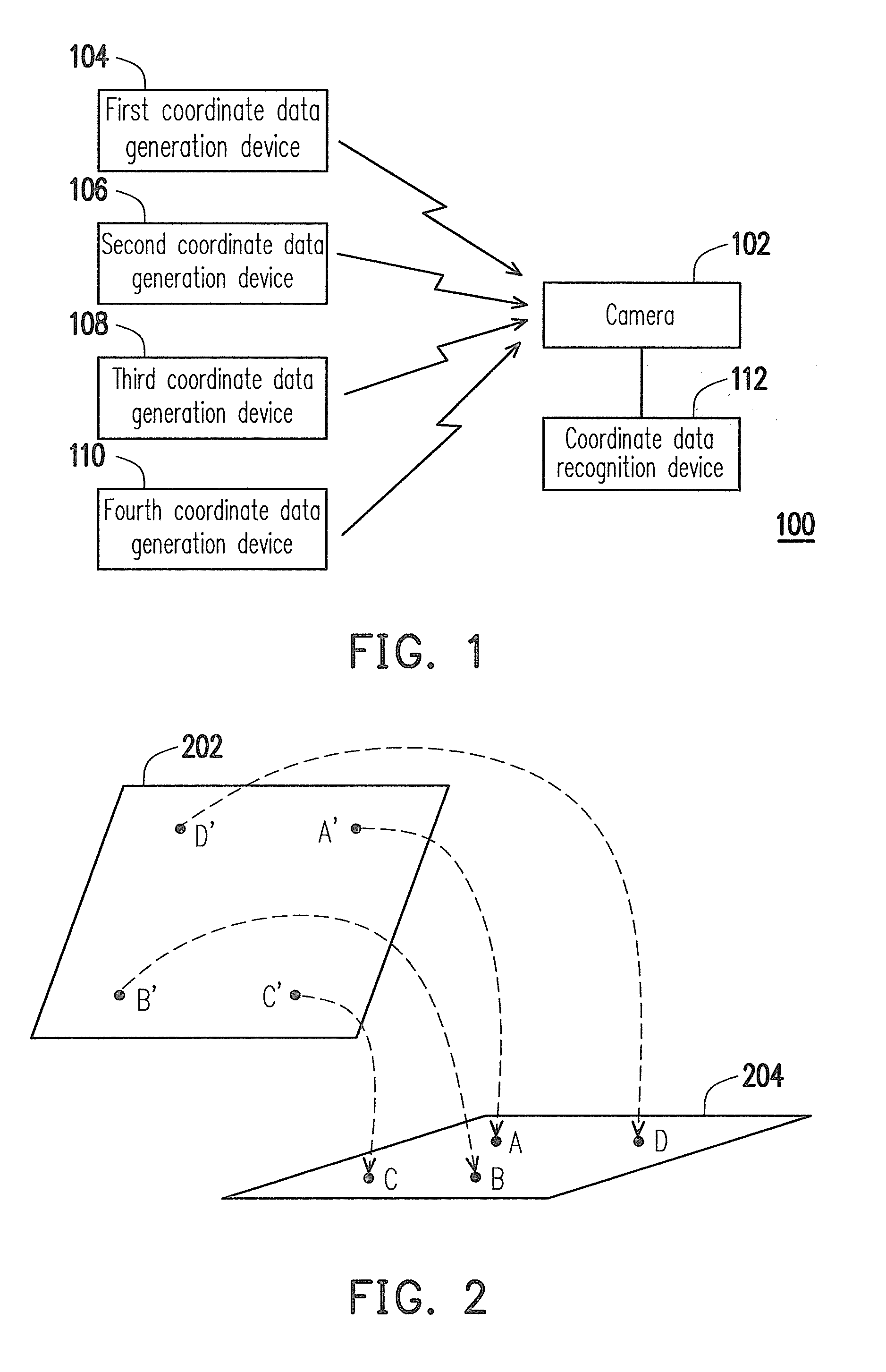
[0034]FIG. 1 is a schematic block diagram of a camera calibration system according to the first exemplary embodiment of the disclosure, and FIG. 2 illustrates the conversion between an image plane and a ground plane in a real scene according to the first exemplary embodiment of the disclosure.

[0035]Referring to FIG. 1, the camera calibration system 100 includes a first coordinate data generation device 104, a second coordinate data generation device 106, a third coordinate data generation device 108, a fourth coordinate data generation device 110, and a coordinate data recognition device 112. The camera calibration system 100 is configured to calibrate a camera 102, wherein the camera 102 is used for capturing an image plane 202 of a real scene to be monitored.

[0036]The first coordinate data generation device 104, the second coordinate data generation device 106, the third coordinate data generation device 108, and the fourth coordinate data generation device 110 generate map coordi...

second exemplary embodiment

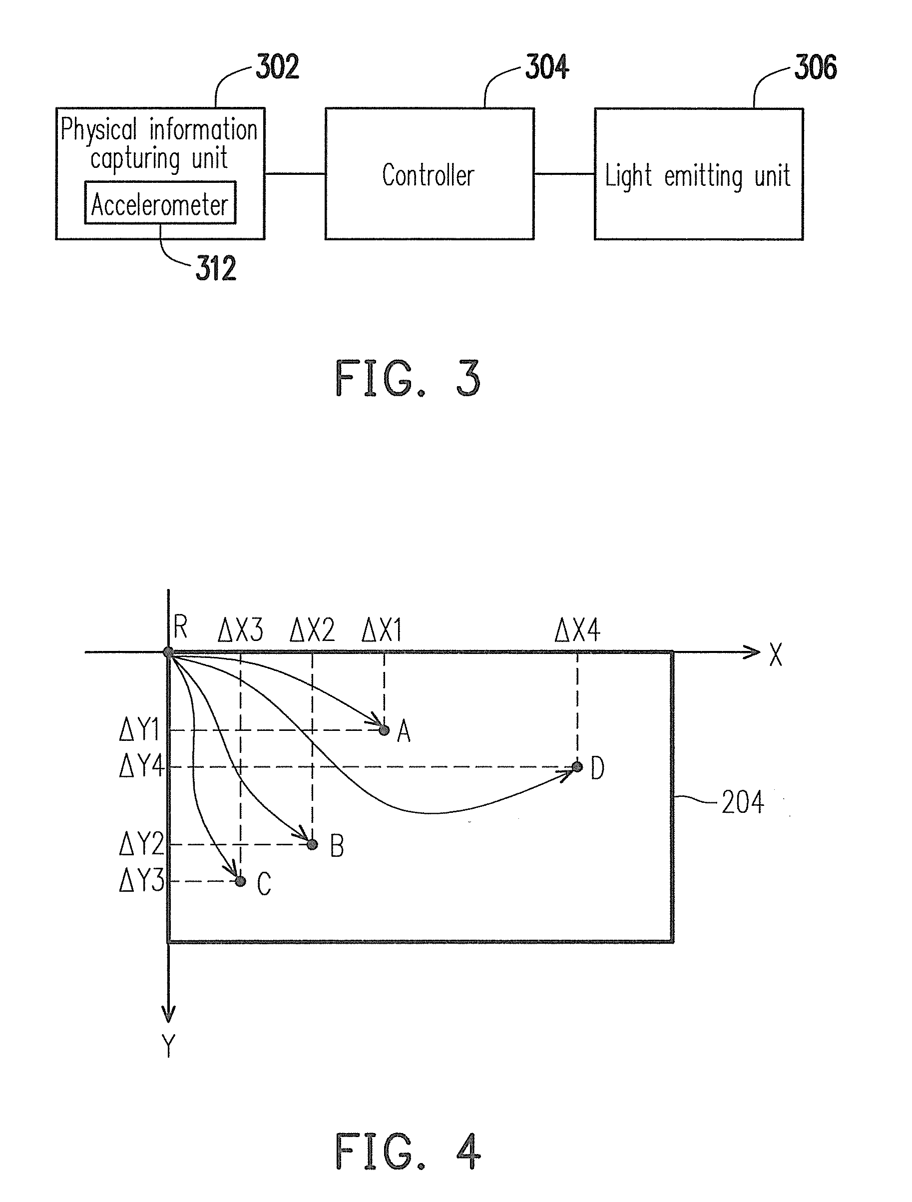
[0065]In the camera calibration system of the first exemplary embodiment, a coordinate data generation device calculates the map coordinate data corresponding to a real position by measuring the acceleration of moving from a reference point to the real position. While in the camera calibration system of the second exemplary embodiment, a coordinate data generation device measures the map coordinate data corresponding to a real position through a laser. Below, the difference between the first exemplary embodiment and the second exemplary embodiment will be described.

[0066]FIG. 9 is a schematic block diagram of a camera calibration system according to the second exemplary embodiment of the disclosure.

[0067]Referring to FIG. 9, the camera calibration system 900 includes a fifth coordinate data generation device 902, a feature point positioning unit 904, and a coordinate data recognition device 112. The camera calibration system 900 is configured to calibrate the camera 102. The coordin...


PUM


Abstract

A camera calibration system including a coordinate data generation device and a coordinate data recognition device is provided. The coordinate data generation device generates a plurality of map coordinate data corresponding to a plurality of real positions in a real scene. The coordinate data recognition device receives an image plane of the real scene from a camera to be calibrated and receives the map coordinate data from the coordinate data generation device. Besides, the coordinate data recognition device recognizes image positions corresponding to the real positions in the image plane and calculates image coordinate data corresponding to the image positions. Moreover, the coordinate data recognition device calculates a coordinate transform matrix corresponding to the camera according to the image coordinate data and the map coordinate data. Thereby, the camera calibration system can finish the calibration of the camera quickly.

Description

CROSS-REFERENCE TO RELATED APPLICATION[0001]This application claims the priority benefit of Taiwan application serial no. 98141037, filed on Dec. 1, 2009. The entirety of the above-mentioned patent application is hereby incorporated by reference herein and made a part of specification.BACKGROUND[0002]1. Field[0003]The disclosure relates to a camera calibration method, and a coordinate data generation method.[0004]2. Description of Related Art[0005]Along with the development of imaging technology, video surveillance systems have been broadly applied in positioning monitored people. In an existing surveillance system, an operator determines the position of a monitored person by directly looking at the surveillance image. However, since the direction and size of the surveillance image are restricted by the deployed position of the camera, the operator cannot instantly determine the position and movement of the monitored person. Especially when the monitored person moves out of the moni...

Claims


Application Information

Patent Timeline
Patent Type & Authority Applications(United States)
IPC IPC(8): H04N17/00
CPCG01B11/03G01B21/042G06T2207/30232G06T2207/30204G06T7/0018G06T7/80
Inventor PAI, HUNG-IHUNG, SHANG-CHIHYUAN, CHII-YAHCHEN, YI-YUANLAN, KUNG-MING
Owner IND TECH RES INST
Why Eureka
Try Eureka