Position detection apparatus, image taking apparatus and position detection method

Inactive Publication Date: 2011-06-02
SONY CORP
View PDF5 Cites 8 Cited by
  • Summary
  • Abstract
  • Description
  • Claims
  • Application Information

AI Technical Summary

Benefits of technology

[0020]As a result, the position detection apparatus according to the embodiment allows the number of signal lin

Problems solved by technology

As a result, the resolution of the l

Method used


Image

  • Position detection apparatus, image taking apparatus and position detection method
  • Position detection apparatus, image taking apparatus and position detection method
  • Position detection apparatus, image taking apparatus and position detection method

Examples


Example

Second Embodiment

[Configuration of Main Sections of the Camera System]
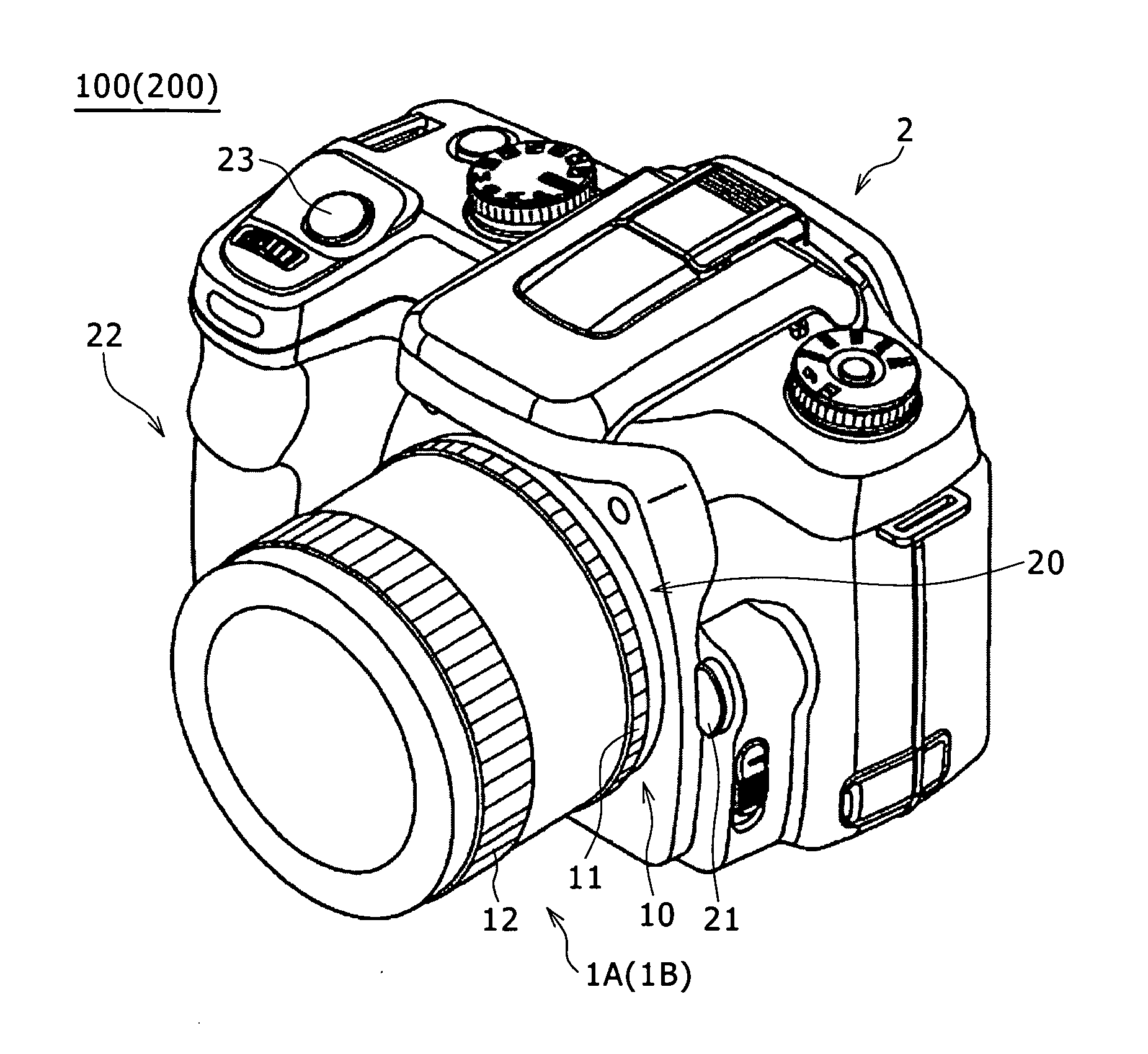
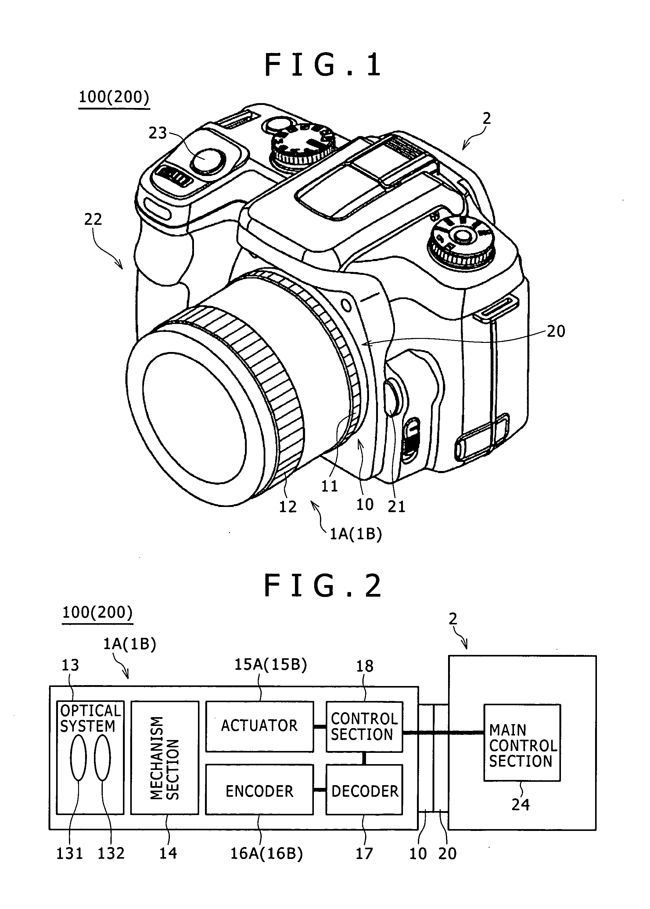
[0064]A camera system 200 according to a second embodiment of the present invention has a configuration similar to the configurations shown in FIGS. 1 and 2 as the configurations of the camera system 100 according to the first embodiment of the present invention. However, the configurations of an actuator 15B and a distance encoder 16B which are employed in a replacement lens unit 1B for the camera system 200 are different from respectively the configurations of the actuator 15A and the distance encoder 16A which are employed in the replacement lens unit 1A for the camera system 100 described earlier. By referring to explanatory diagrams of FIGS. 7A, 7B and 8, the following description explains the configurations of the actuator 15B and the distance encoder 16B which are employed in the replacement lens unit 1B for the camera system 200 according to the second embodiment.

[0065]FIGS. 7A and 7B are explanatory diagr...

Example

[0076]The distance encoder 16A of the first embodiment and the distance encoder 16B of the second embodiment do not have to be absolutely encoders of the magnetic type. For example, the distance encoder 16A (16B) can also be an encoder of the optical type. As another typical alternative, the distance encoder 16A (16B) can also be an encoder which has an encoder brush brought into contact with the signal lines.

[0077]In the case of the first embodiment described above, it is not necessary to set the pitch of the bits on the second signal line 162 always at a value equal to the pitch of the bits on the first signal line 161. For example, the pitch of the bits on the second signal line 162 can also be set at a value which is (1 / n) times the pitch of the bits on the first signal line 161 where n≧2. By the same token, in the case of the second embodiment described above, it is not necessary to set the driving step width of the magnetic sensor section 163B explained earlier always at a val...


PUM


Abstract

Disclosed herein is a position detection apparatus including: a signal line along which a bit array including a plurality of bits used for expressing information on one of absolute positions in a direction determined in advance is created repeatedly in the direction determined in advance; and an information reading-out section which is capable of making a movement relative to the signal line in the direction determined in advance in accordance with a driving operation carried out by driving means determined in advance and is used for reading out the information expressed by the bits from the signal line.

Description

CROSS-REFERENCE TO RELATED APPLICATION[0001]The present application claims priority from Japanese Patent Application No. JP 2009-269409 filed in the Japanese Patent Office on Nov. 27, 2009, the entire content of which is incorporated herein by reference.BACKGROUND OF THE INVENTION[0002]1. Field of the Invention[0003]The present invention relates to a technology of a position detection apparatus having a signal line along which bit arrays are created in a direction determined in advance to serve as the direction of the signal line.[0004]2. Description of the Related Art[0005]In an image taking apparatus such as a digital camera, it is necessary to detect the position of a lens by typically execution of an AF (Auto Focus) control. In the process of detecting the position of the lens, however, an absolute-type encoder for detecting an absolute position is used. The absolute-type encoder typically detects an absolute position by carrying out parallel communications from a number of sign...

Claims


Application Information

Patent Timeline
IPC IPC(8): H04N5/228G03B43/00
CPCG01D5/2497G03B19/12G03B3/00
Inventor YANO, HITOSHIONISHI, KATSUHIRO
Owner SONY CORP
Why Eureka
Try Eureka