Zoom lens system, imaging device and camera

Inactive Publication Date: 2011-06-02
PANASONIC CORP
View PDF10 Cites 12 Cited by
  • Summary
  • Abstract
  • Description
  • Claims
  • Application Information

AI Technical Summary

Benefits of technology

[0139]According to the present invention, it is possible to provide: a zoom lens system having a high resolution and a short overall optical length (overall length of lens system), and still having a view angle of 70° or greater at a wide-angle limit, which

Problems solved by technology

However, the zoom lens systems disclosed in the respective patent literatures cannot meet the recent demands in terms of achieving a wider angle and a smaller siz

Method used


Image

  • Zoom lens system, imaging device and camera
  • Zoom lens system, imaging device and camera
  • Zoom lens system, imaging device and camera

Examples


embodiments 1 to 8

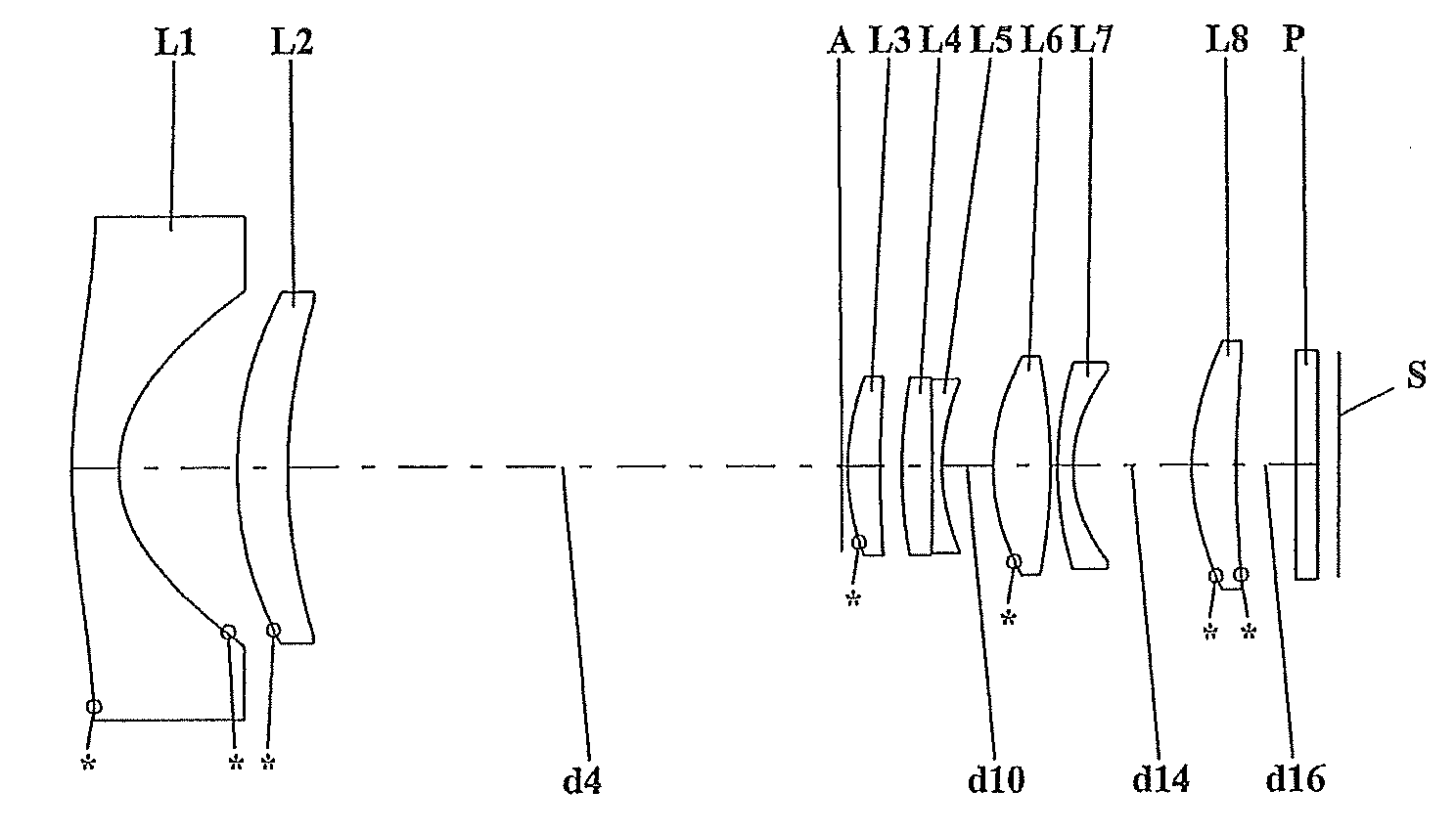
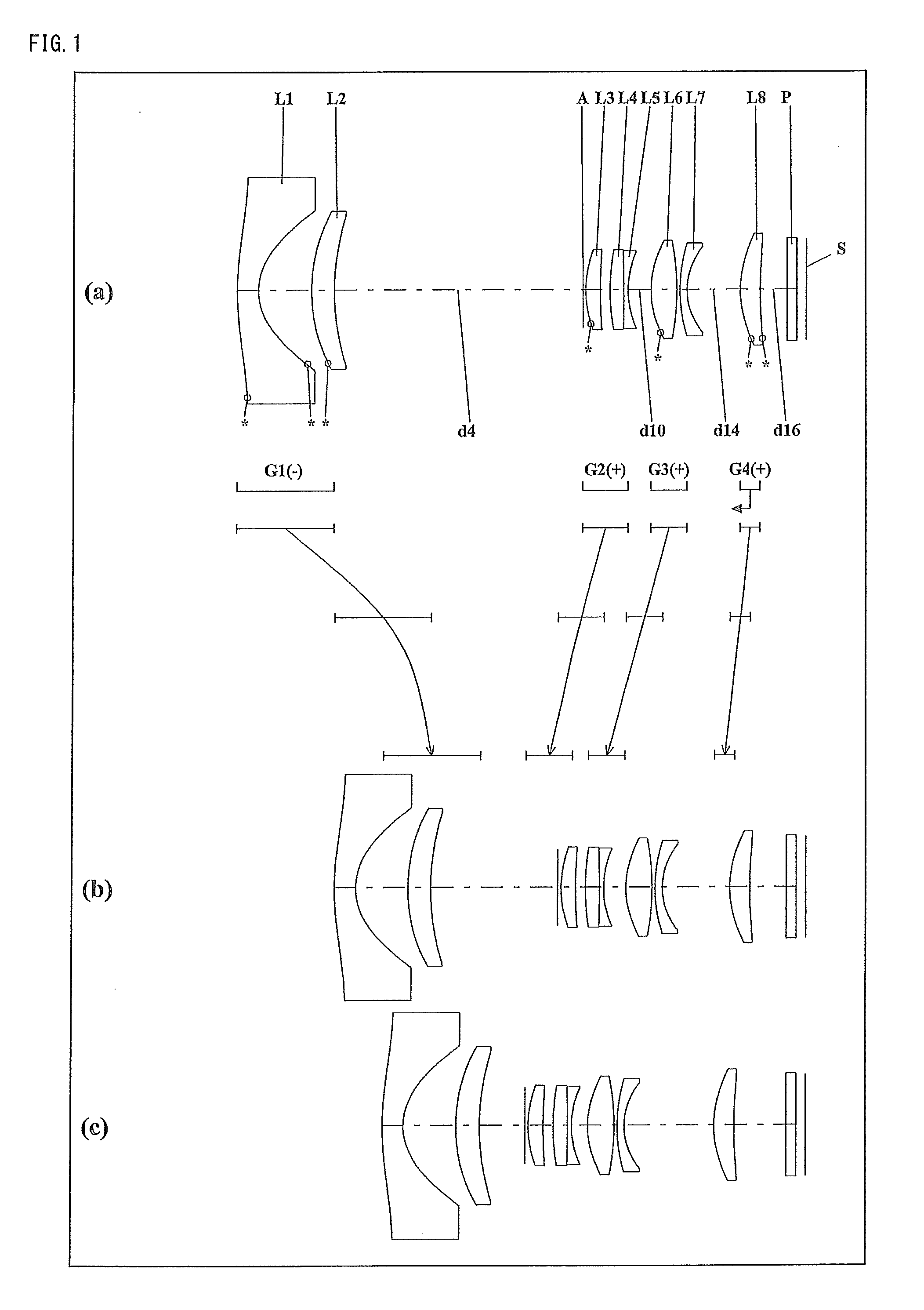
[0181]FIGS. 1, 4, 7, 10, 13, 16, 19 and 22 are lens arrangement diagrams of zoom lens systems according to Embodiments 1 to 8, respectively.

[0182]Each of FIGS. 1, 4, 7, 10, 13, 16, 19 and 22 shows a zoom lens system in an infinity in-focus condition. In each Fig., part (a) shows a lens configuration at a wide-angle limit (in the minimum focal length condition: focal length fW), part (b) shows a lens configuration at a middle position (in an intermediate focal length condition: focal length fM=√(fW*fT)), and part (c) shows a lens configuration at a telephoto limit (in the maximum focal length condition: focal length fT). Further, in each Fig., an arrow of straight or curved line provided between part (a) and part (b) indicates the movement of each lens unit from a wide-angle limit through a middle position to a telephoto limit. Moreover, in each Fig., an arrow imparted to a lens unit indicates focusing from an infinity in-focus condition to a close-object in-focus condition. That is,...

embodiment 9

[0306]FIG. 25 is a schematic construction diagram of a digital still camera according to Embodiment 9. In FIG. 25, the digital still camera comprises: an imaging device having a zoom lens system 1 and an image sensor 2 composed of a CCD; a liquid crystal display monitor 3; and a body 4. The employed zoom lens system 1 is a zoom lens system according to Embodiment 1. In FIG. 25, the zoom lens system 1 comprises a first lens unit G1, an aperture diaphragm A, a second lens unit G2, a third lens unit G3, and a fourth lens unit G4. In the body 4, the zoom lens system 1 is arranged on the front side, while the image sensor 2 is arranged on the rear side of the zoom lens system 1. On the rear side of the body 4, the liquid crystal display monitor 3 is arranged, while an optical image of a photographic object generated by the zoom lens system 1 is formed on an image surface S.

[0307]A lens barrel comprises a main barrel 5, a moving barrel 6 and a cylindrical cam 7. When the cylindrical cam 7...

embodiments 10 to 14

[0312]FIGS. 26, 29, 32, 35 and 38 are lens arrangement diagrams of zoom lens systems according to Embodiments 10 to 14, respectively.

[0313]Each of FIGS. 26, 29, 32, 35 and 38 shows a zoom lens system in an infinity in-focus condition. In each Fig., part (a) shows a lens configuration at a wide-angle limit (in the minimum focal length condition: focal length fW), part (b) shows a lens configuration at a middle position (in an intermediate focal length condition: focal length fM=√(fW*fT)), and part (c) shows a lens configuration at a telephoto limit (in the maximum focal length condition: focal length fT). Further, in each Fig., an arrow of straight or curved line provided between part (a) and part (b) indicates the movement of each lens unit from a wide-angle limit through a middle position to a telephoto limit. Moreover, in each Fig., an arrow imparted to a lens unit indicates focusing from an infinity in-focus condition to a close-object in-focus condition. That is, the arrow indic...


PUM


Abstract

A zoom lens system, in order from an object side to an image side, comprising a first lens unit having negative optical power, a second lens unit having positive optical power, a third lens unit having positive optical power, and a fourth lens unit having positive optical power, wherein in zooming, the intervals between the respective lens units vary, and the condition (I-1): 2ωW/FW≧34 (fT/fW>2.0, ωW: a half view angle (°) at a wide-angle limit, FW: an F-number at a wide-angle limit, fT: a focal length of the entire system at a telephoto limit, fW: a focal length of the entire system at a wide-angle limit) is satisfied, having a high resolution and a short overall optical length (overall length of lens system), and still having a view angle of 70° or greater at a wide-angle limit, which is satisfactorily adaptable for wide-angle image taking, and yet having a large aperture with an F-number of about 2.0 at a wide-angle limit; an imaging device; and a camera.

Description

TECHNICAL FIELD[0001]The present invention relates to a zoom lens system, an imaging device and a camera. In particular, the present invention relates to: a zoom lens system having a high resolution and a short overall optical length (overall length of lens system), and still having a view angle of 70° or greater at a wide-angle limit, which is satisfactorily adaptable for wide-angle image taking, and yet having a large aperture with an F-number of about 2.0 at a wide-angle limit; an imaging device employing the zoom lens system; and a thin and very compact camera employing the imaging device.BACKGROUND ART[0002]With recent progress in the development of solid-state image sensors such as CCD (Charge Coupled Device) and CMOS (Complementary Metal-Oxide Semiconductor) having high pixel density, digital still cameras and digital video cameras (simply referred to as “digital cameras”, hereinafter), which employ an imaging device including an imaging optical system of high optical perform...

Claims


Application Information

Patent Timeline
IPC IPC(8): H04N5/262G02B15/14
CPCG02B15/177G02B15/144515
Inventor IIYAMA, TOMOKOYOSHITSUGU, KEIKI
Owner PANASONIC CORP
Why Eureka
Try Eureka