Sensor device, method of driving sensor element, display device with input function, electronic unit and radiation image pickup device

a technology of sensor element and display device, which is applied in the direction of optical radiation measurement, instruments, television systems, etc., can solve the problems of insufficient reset of electric charge stored in storage capacity, inability to take sufficient measures, and difficulty in obtaining satisfactory detection, etc., to reduce afterimages, stable detection operation, and reduce afterimages

Active Publication Date: 2011-06-02
JAPAN DISPLAY INC
View PDF10 Cites 66 Cited by
  • Summary
  • Abstract
  • Description
  • Claims
  • Application Information

AI Technical Summary

Benefits of technology

[0015]In the sensor device, the method of driving the sensor element, the display device with the input function, the electronic unit, or the radiation image pickup device according to the embodiment of the present invention, the electric charge according to the amount of received light is generated in the photoelectric conversion element. Subsequently, the electric charge converted by the photoelectric conversion element is stored in the charge storage section, and the electric charge stored in the charge storage section or the voltage value according to the stored electric charge is output as the sensor detection signal. The electric charge stored in the charge storage section is reset by supply of the predetermined reset voltage to the charge storage section. At the time, by continuously or intermittently supplying the predetermined reset voltage to the charge storage section over the period exceeding one horizontal scan period, it may be possible to reliably reset the electric charge stored in the charge storage section so as to reduce afterimages, even when, for example, the photoelectric conversion element is in a saturated state.
[0016]According to the sensor device, the method of driving the sensor element, the display device with the input function, the electronic unit, or the radiation image pickup device in the embodiment of the present invention, the predetermined reset voltage is supplied to the charge storage section continuously or intermittently over the period exceeding one horizontal scan period and thus, it may be possible to perform stable detection operation (image-pickup operation) by reliably resetting the electric charge stored in the charge storage section so as to reduce afterimages, even when, for example, the photoelectric conversion element is in a saturated state.

Problems solved by technology

When the pre-reset state of the storage capacity remains, a so-called afterimage occurs at the time of the subsequent reading operation, making it difficult to obtain a satisfactory detection result.
However, in such a technique of the past, sufficient measures are not taken to deal with a problem of an afterimage that occurs in a case in which a PIN photodiode having a gate electrode is used as the photoelectric conversion element.
In particular, there is such a problem that even when a reset voltage is supplied for a short period of time after the i-layer enters the storage state, the electric charge stored in the storage capacity cannot be sufficiently reset and thus, a remedy to address this problem is desired.

Method used


Image

  • Sensor device, method of driving sensor element, display device with input function, electronic unit and radiation image pickup device
  • Sensor device, method of driving sensor element, display device with input function, electronic unit and radiation image pickup device
  • Sensor device, method of driving sensor element, display device with input function, electronic unit and radiation image pickup device

Examples


application examples

MODULE AND APPLICATION EXAMPLES

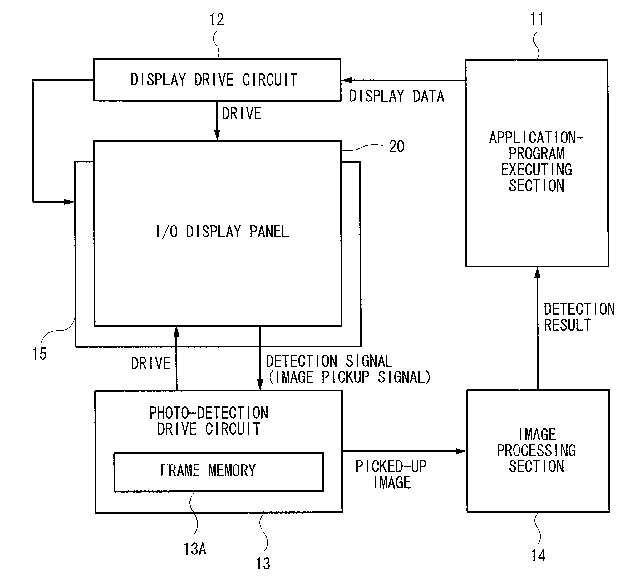
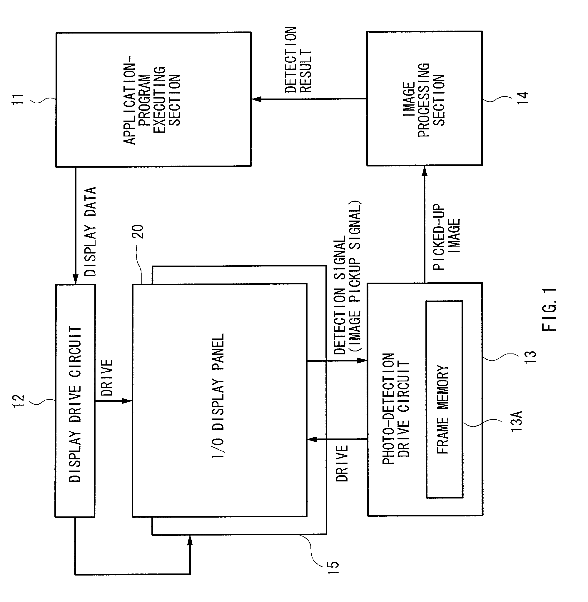
[0150]Next, with reference to FIG. 19 through FIG. 23G, there will be described application examples of the display device with the input function described above. This display device can be applied to electronic units in all fields, which display externally-input video signals or internally-generated video signals as still or moving images. For example, the display device can be applied to electronic units such as television receivers, digital cameras, laptop computers, portable terminal devices such as portable telephones, and video cameras.

application example 1

[0151]FIG. 19 illustrates an external view of a television receiver serving as a first example of the electronic units. This television receiver has, for example, a video display screen section 510 including a front panel 511 and a filter glass 512. The display device with the input function described above can be applied to the video display screen section 510 of this television receiver.

application example 2

[0152]FIGS. 20A and 20B are external views of a digital camera serving as a second example of the electronic units. This digital camera includes, for example, a flash emitting section 521, a display section 522, a menu switch 523, and a shutter button 524. The display device with the input function described above can be applied to the display section 522 of this digital camera.


PUM


Abstract

A sensor device includes sensor elements two-dimensionally arranged and a sensor driving section driving the sensor elements. Each of the sensor elements includes a photoelectric conversion element generating electric charge according to an amount of received light, a charge storage section connected to one end of the photoelectric conversion element and storing electric charge generated by the photoelectric conversion element, a readout section reading either a voltage value resulted from the electric charge in the charge storage section or the stored electric charge, to output the read voltage value or the read electric charge and a reset section resetting the electric charge in the charge storage section through supplying a predetermined reset voltage to the charge storage section. The sensor driving section controls the reset section so that the predetermined reset voltage is continuously or intermittently supplied to the charge storage section over a period exceeding one horizontal scan period.

Description

BACKGROUND OF THE INVENTION[0001]1. Field of the Invention[0002]The present invention relates to a sensor device picking up an image of an object and detecting the position of a proximity object, a method of diving a sensor element applied to such a sensor device, a display device with an input function, which includes a sensor function (input function) and a display function, and an electronic unit including such a display device. The present invention also relates to a radiation image pickup device reading information based on radiation by converting the waveform of radiation represented by alpha-ray, beta-ray, gamma-ray, and X-ray.[0003]2. Description of the Related Art[0004]Previously, there has been known an optical sensor device including a sensor panel in which photoelectric conversion elements are arranged in a matrix form (Japanese Unexamined Patent Application Publications No. 09-92807 and No. 2001-345440). Further, there has been developed a display device in which displa...

Claims


Application Information

Patent Timeline
Patent Type & Authority Applications(United States)
IPC IPC(8): H04N5/335G06F3/042G06F3/038G01J1/42
CPCG06F3/0412G06F3/0488G06F3/042G06F3/0416
Inventor TAKATOKU, MAKOTOSENDA, MICHIRU
Owner JAPAN DISPLAY INC
Why Eureka
Try Eureka