Eye refractive power measurement apparatus

a technology of refractive power measurement and eye, which is applied in the field of eye refractive power measurement apparatus, can solve the problems of low reliability coefficient, difficult to specify this region with irregular astigmatism, and displacement level in the entire ey

Inactive Publication Date: 2011-06-02
NIDEK CO LTD
View PDF4 Cites 7 Cited by
  • Summary
  • Abstract
  • Description
  • Claims
  • Application Information

AI Technical Summary

Benefits of technology

[0009]In view of the above problems, a technical object of the present invention is to provide an eye refractive power measurement apparatus for allowing an examiner to specify with ease an error region and a region other than the error region in a measurement region.
[0012]According to the present invention, an examiner can specify with ease an error region and a region other than the error region in a measurement region.

Problems solved by technology

However, the conventional apparatus shows a displacement level in the entire eye by means of the reliability coefficient.
Therefore, when a certain region has irregular astigmatism, it is difficult to specify this region having irregular astigmatism.
Further, although there is a normal region where irregular astigmatism is not likely to exist, a low reliability coefficient is calculated due to the partial region having irregular astigmatism.

Method used


Image

  • Eye refractive power measurement apparatus
  • Eye refractive power measurement apparatus
  • Eye refractive power measurement apparatus

Examples


Embodiment Construction

[0024]Preferred embodiments of the present invention will be described below with reference to the accompanying drawings, in which like reference characters designate similar or identical parts throughout the several views thereof.

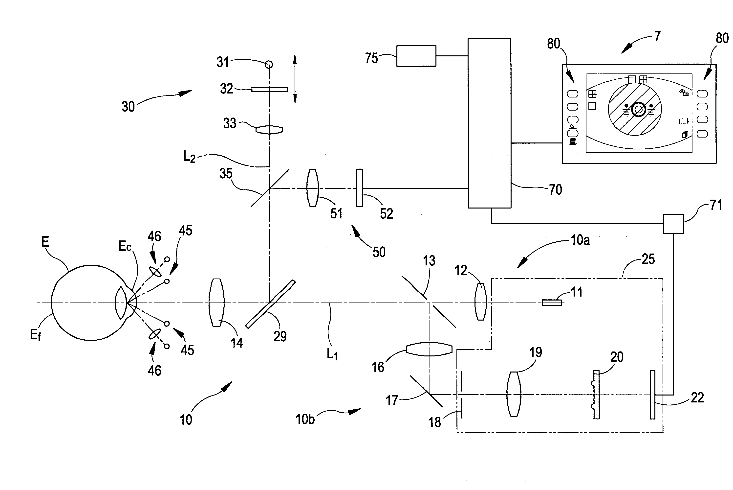
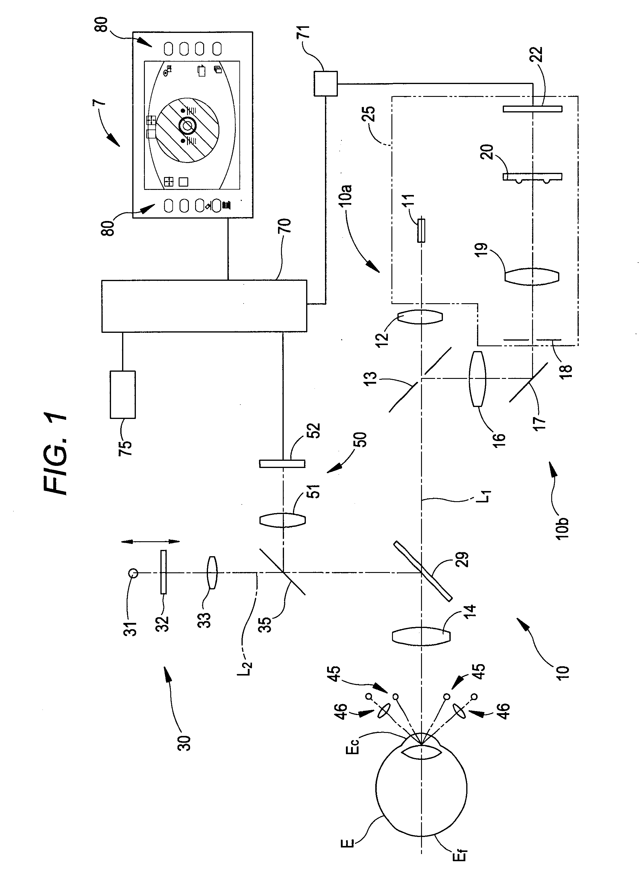
[0025]FIG. 1 is a view illustrating a schematic configuration of an optical system and a control system in an apparatus according to one embodiment of the present invention. A measurement optical system 10 is configured with a projecting optical system 10a and a light receiving optical system 10b. The projecting optical system 10a projects a spot-shaped measurement target onto a fundus Ef of an eye E via a center of a pupil of the eye E. The light receiving optical system 10b extracts light, reflected from the fundus Ef, in a ring shape via a periphery of the pupil of the eye E, and causes a two-dimensional imaging device to capture (receive) a ring-shaped image.

[0026]The projecting optical system 10a includes a measurement light source 11, a relay lens 12...


PUM


Abstract

An eye refractive power measurement apparatus includes a measurement optical system, a calculator and an output unit. The measurement optical system projects measurement light onto a fundus of an examinee's eye, extracts the measurement light reflected on the fundus as ring-shaped light, and causes an imaging device to capture a ring-shaped image. The calculator measures eye refractive power of the examinee's eye, based on the ring-shaped image captured by the imaging device, specifies a position of the ring-shaped image to calculate a measured line of the image, performs approximate processing on the measured line to calculate an approximate curve, and calculates a displacement between the measured line and the approximate curve in a meridian direction for each divided region. The output unit outputs a measurement result of the eye refractive power and a calculation result of the displacement in each divided region.

Description

CROSS-REFERENCE TO RELATED APPLICATION[0001]This application is based on Japanese Patent Application No. 2009-274058 filed with the Japan Patent Office on Dec. 2, 2009, the entire content of which is hereby incorporated by reference.BACKGROUND[0002]1. Technical Field[0003]The present invention relates to an eye refractive power measurement apparatus which measures refractive power of an examinee's eye.[0004]2. Related Art[0005]There is known an eye refractive power measurement apparatus which projects measurement light onto a fundus of an examinee's eye, extracts the light reflected on the fundus as a ring image, causes a two-dimensional imaging device to capture this ring image, and measures eye refractive power, based on the captured ring image. In such an apparatus, a reliability coefficient is displayed on a monitor (refer to Patent Document 1). The reliability coefficient is obtained in such a manner that each of differences between a measured line, obtained by sequentially det...

Claims


Application Information

Patent Timeline
IPC IPC(8): A61B3/103
CPCA61B3/103
Inventor NAKAMURA, KENJI
Owner NIDEK CO LTD
Why Eureka
Try Eureka