
Flat secondary battery and method of manufacturing the same

a secondary battery and flat technology, applied in the field of flat secondary batteries, can solve the problems of increased risk of internal short-circuiting and damage, and achieve the effect of excellent impact resistan

Inactive Publication Date: 2011-06-02
SHARP KK
View PDF1 Cites 36 Cited by
  • Summary
  • Abstract
  • Description
  • Claims
  • Application Information

AI Technical Summary

Benefits of technology

[0026]According to the present invention, it is possible to obtain a flat secondary battery excellent in impact resistance such that, even with a vibration, an impact and the like during a distribution course and in a usage environment, there is no internal short-circuiting due to disturbance of an electrode laminated structure and damage to a separator by a pointed corner of an electrode.

Problems solved by technology

Therefore, the flat secondary battery has a problem in that a risk of occurrence of internal short-circuiting is increased as a result of damage to the bag-like separator by the pointed corner when a vibration or an impact from the outside is received.
Therefore, it is easily supposed that a rate of occurrence of damage to a separator and a rate of occurrence of internal short-circuiting, which goes along therewith, are ten times of those of the cylindrical secondary battery.

Method used


Image

  • Flat secondary battery and method of manufacturing the same
  • Flat secondary battery and method of manufacturing the same
  • Flat secondary battery and method of manufacturing the same

Examples


embodiment 1

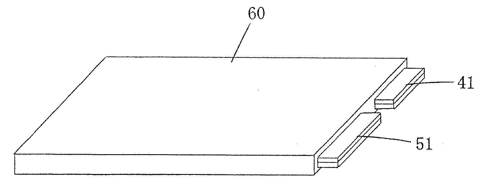
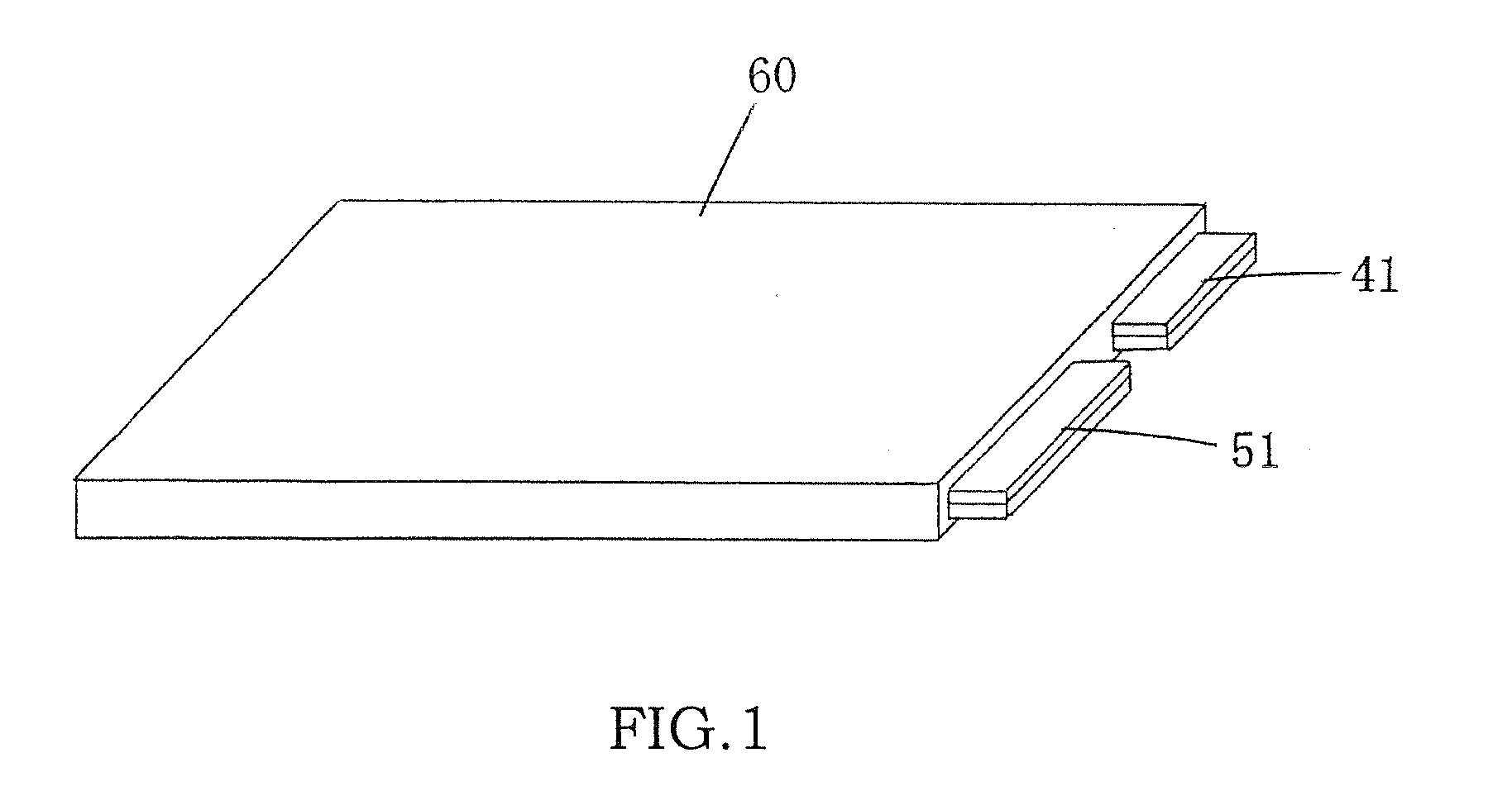
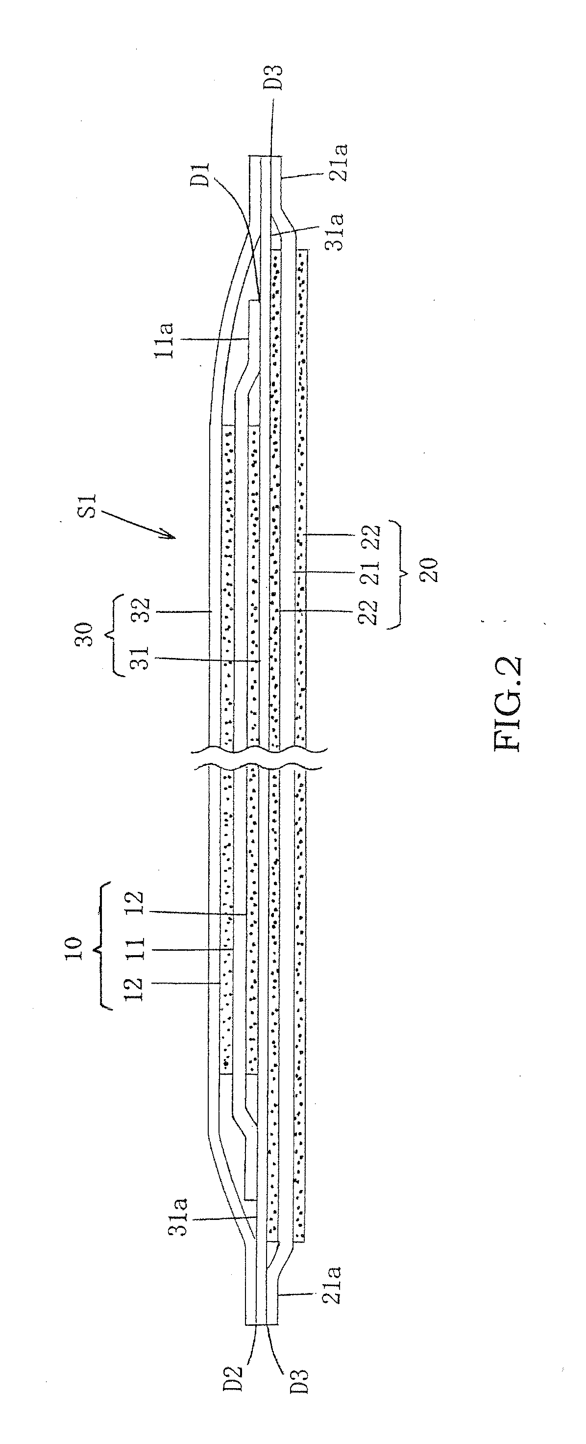
[0081]FIG. 1 is a perspective view showing Embodiment 1 of a flat secondary battery of the present invention. FIG. 2 is a schematic sectional view showing an internal laminated structure in the flat secondary battery of Embodiment 1. FIGS. 3(A) to 3(E) are process explanatory views each showing part of a process of manufacturing the flat secondary battery of Embodiment 1.

[0082]This laminated-type secondary battery includes one positive-electrode plate 10, one negative-electrode plate 20, a bag-like separator 30 for preventing physical and electrical contact of the positive-electrode plate 10 and the negative-electrode plate 20, a positive-electrode lead plate 40 electrically connected to the positive-electrode plate 10, a positive-electrode terminal plate 41 bonded to the positive-electrode lead plate 40, a negative-electrode lead plate 50 electrically connected to the negative-electrode plate 20, a negative-electrode terminal plate 51 bonded to the negative-electrode lead plate 50,...

embodiment 2

[0114]FIGS. 4(A) and 4(B) are process explanatory views each showing part of a process of manufacturing a flat secondary battery in Embodiment 2 of the present invention.

[0115]Embodiment 2 is a flat secondary battery in which a plurality of (e.g., five) battery modules S1 of Embodiment 1 shown in FIGS. 2 and 3 are included. It should be noted that, in FIG. 4, the same elements as those of Embodiment 1 shown in FIGS. 2 and 3 are denoted by the same symbols. Hereinafter, the configuration in Embodiment 2 that is different from that in Embodiment 1 is mainly described.

[0116]In the case of Embodiment 2, in the above-mentioned step (C), as shown in FIG. 4(A), a plurality of battery modules S1 are formed for one flat secondary battery. As shown in FIG. 4(B), in a state where the plurality of battery modules S1 are mutually stacked, a plurality of lead plates of the positive electrodes are mutually stacked, sandwiched by the positive-electrode terminal plates, and bonded, and a plurality o...

embodiment 3

[0123]FIGS. 5(A) to 5(E) are process explanatory views each showing part of a process of manufacturing a flat secondary battery in Embodiment 3 of the present invention.

[0124]Embodiment 3 has a configuration similar to that of Embodiment 1 except that forms of bonded portions of a positive-electrode plate 110 and a negative-electrode plate 120 in a battery module S2 are different from those in Embodiment 1. It should be noted that, in FIG. 5, the same elements as those of Embodiment 1 shown in FIGS. 2 and 3 are denoted by the same symbols. Hereinafter, the configuration of points in Embodiment 3 that are different from those in Embodiment 1 is mainly described.

[0125]In the case of the battery module S2 of Embodiment 3, as shown in FIG. 5(A), the positive-electrode plate 110 has a positive-electrode non-coated portion 111a on both surfaces on the side of one short side of the positive-electrode current collector sheet 11, and the positive-electrode active-material layer 12 is formed ...


PUM

PropertyMeasurementUnit
Sizeaaaaaaaaaa
Electrical conductoraaaaaaaaaa
Areaaaaaaaaaaa

Abstract

A flat secondary battery comprising: a positive electrode plate; a negative electrode plate opposed to the positive electrode plate; an electrolytic solution being present between the electrode plates; a separator interposed between the electrode plates; and a covering material for sealing the electrolytic solution, whereinthe positive electrode plate includes: a positive-electrode current-collector sheet whose peripheral area has a bonding area bonded to a peripheral area of the separator; and a positive-electrode active-material layer laminated on a non-bonding area of one surface or both surfaces of the positive-electrode current-collector sheet,the negative-electrode plate includes: a negative-electrode current-collector sheet whose peripheral area has a bonding area bonded to the peripheral area of the separator; and a negative-electrode active-material layer laminated on a non-bonding area of one surface or both surfaces of the negative-electrode current-collector sheet and having a sufficient size to cover the positive-electrode active-material layer, andthe peripheral areas of both surfaces of the separator are bonded to the bonding areas of the positive-electrode current-collector sheet and the negative-electrode current-collector sheet to maintain a state in which an area of the negative-electrode active-material layer entirely covers an area of the positive-electrode active-material layer so that a battery module is formed.

Description

TECHNICAL FIELD[0001]The present invention relates to a flat secondary battery and a method of manufacturing the same.BACKGROUND ART[0002]As conventional secondary batteries, there have been cylindrical and flat secondary batteries.[0003]In a cylindrical secondary battery, typically, one band-shaped positive-electrode plate and one band-shaped negative-electrode plate are stacked with a band-shaped separator therebetween, and the stacked plates are spirally wound, so that an electrode group is formed. In this case, there are eight pointed corners in the electrode group, namely, four pointed corners of the positive-electrode plate and four pointed corners of the negative-electrode plate.[0004]On the other hand, as a flat secondary battery of a quadrangular type or a laminated sealing type, Prior Art 1 is known in which, with a strip-shaped positive-electrode plate or a negative-electrode plate contained in a bag-like separator, the plurality of positive-electrode plates and the plura...

Claims


Application Information

Patent Timeline
IPC IPC(8): H01M10/0585H01M6/02H01M50/417
CPCH01M4/661H01M4/667H01M4/668H01M10/0436H01M10/052Y10T29/4911H01M10/30H01M10/345H01M2/162H01M2/1653H01M2/1673H01M10/0585Y02E60/10H01M50/44H01M50/46Y02P70/50H01M50/417
Inventor YONEDA, TETSUYA
Owner SHARP KK
Learn More