
Coin feeding device and coin handling machine

a coin feeding device and coin processing technology, which is applied in the direction of coin counters, coin/paper handlers, instruments, etc., can solve the problems of coin that has been brought up at a high speed along with the rotating rotary disc b, and the coin that has been impinged on the protruding member, so as to increase the processing speed of coins of the coin feeding devi

Active Publication Date: 2011-06-02
GLORY KOGYO KK
View PDF8 Cites 8 Cited by
  • Summary
  • Abstract
  • Description
  • Claims
  • Application Information

AI Technical Summary

Benefits of technology

[0007]The present invention has been made in view of the above circumstances. The object of the present invention is to provide a coin feeding device capable of sending coins one by one from a rotary disc to a coin transport mechanism, even when the rotary disc is rotated at a high speed, so that normal coins can be stably fed one by one from a coin storage space, whereby a processing speed of coins can be increased, and to provide a coin handling machine including the coin feeding device.
[0009]According to such a coin feeding device, the first guide member, which is configured to guide, in the upper area of the rotary disc, coins which have been transported by the respective protruding members to the coin transport mechanism, is stationarily provided on a position that is nearer to the center of the rotary disc than the respective protruding members of the rotary disc. Thus, even when the rotary disc is rotated at a high speed, there is no possibility that the coins transported in the upper area of the rotary disc by the respective protruding members might be sandwiched between the rotary disc and the first guide member, and therefore the coins can be stably sent one by one from the rotary disc to the coin transport mechanism. Thus, the normal coins can be stably fed one by one from the coin storage space to the outside thereof. As a result, a processing speed of coins of the coin feeding device can be increased as compared with that of the conventional money feeding device.
[0014]According to such a coin feeding device, when two or more coins in a superposed state are transported by the one protruding member from the lower area of the rotary disc, the second guide member guides the coin lying upon the other coin(s) on the rotary disc radially outward from the rotary disc by the centrifugal force of the rotary disc. The coin, which has been guided radially outward from the rotary disc, is disengaged from the protruding member so as to be returned to the lower area of the rotary disc by its own weight. Since such a second guide member is provided, when two or more coins in a superposed state are transported by the one protruding member from the lower area of the rotary disc, the coin(s) lying upon the other coin(s) on the rotary disc can be returned to the lower area of the rotary disc by its (their) own weight(s). Thus, a processing speed of coins of the coin feeding device can be increased as compared with that of the conventional money feeding device. Even when two or more coins in a superposed state are transported by the one protruding member from the lower area of the rotary disc, the coin(s) lying upon the other coin(s) on the rotary disc can be returned to the lower area of the rotary disc by the second guide member.
[0017]According to such a coin feeding device, since the lever member is disposed in the vicinity of the edge of the rotary disc, with a gap through which one normal coin can pass being defined between the lever member and the surface of the rotary disc on the side of the coin storage space, two or more coins in a superposed state can be restrained from being sent from the lower area of the rotary disc to the upper area thereof. Thus, a processing speed of coins of the coin feeding device can be increased as compared with that of the conventional money feeding device. Even when two or more coins in a superposed state are transported by the one protruding member from the lower area of the rotary disc, the coin(s) lying upon the other coin on the rotary disc can be returned to the lower area of the rotary disc by the lever member.
[0021]According to such a coin feeding device, since the third member is provided such that a gap through which one normal coin can pass is defined between the third guide member and the surface of the rotary disc on the side of the coin storage space, two or more coins in a superposed state can be restrained from being sent to the coin transport mechanism. Thus, a processing speed of coins of the coin feeding device can be increased as compared with that of the conventional money feeding device. Even when two or more coins in a superposed state are transported by the one protruding member from the lower area of the rotary disc, the coin(s) lying upon the other coin on the rotary disc can be returned to the lower area of the rotary disc by the third guide member.

Problems solved by technology

However, the conventional coin feeding device 90 shown in FIG. 12 has a problem in that it is difficult to increase a processing speed of coins, i.e., an amount of coins to be fed out from the coin feeding device 90 within a certain period.
Furthermore, when the rotary speed of the rotary disc 92 is increased, there occurs a problem in that a coin that has been brought up at a high speed along with the rotating rotary disc 92 might impinge on the protruding member 94 and rebound therefrom.
Namely, the behavior of a coin becomes unstable.
In the coin feeding device 90 disclosed in JP8-212407A and JP8-212408A, for example, when the rotary speed of the rotary disc 92 is increased, there occurs a problem in that it is difficult to stably feed coins from the coin storage space 99.

Method used


Image

  • Coin feeding device and coin handling machine
  • Coin feeding device and coin handling machine
  • Coin feeding device and coin handling machine

Examples


Embodiment Construction

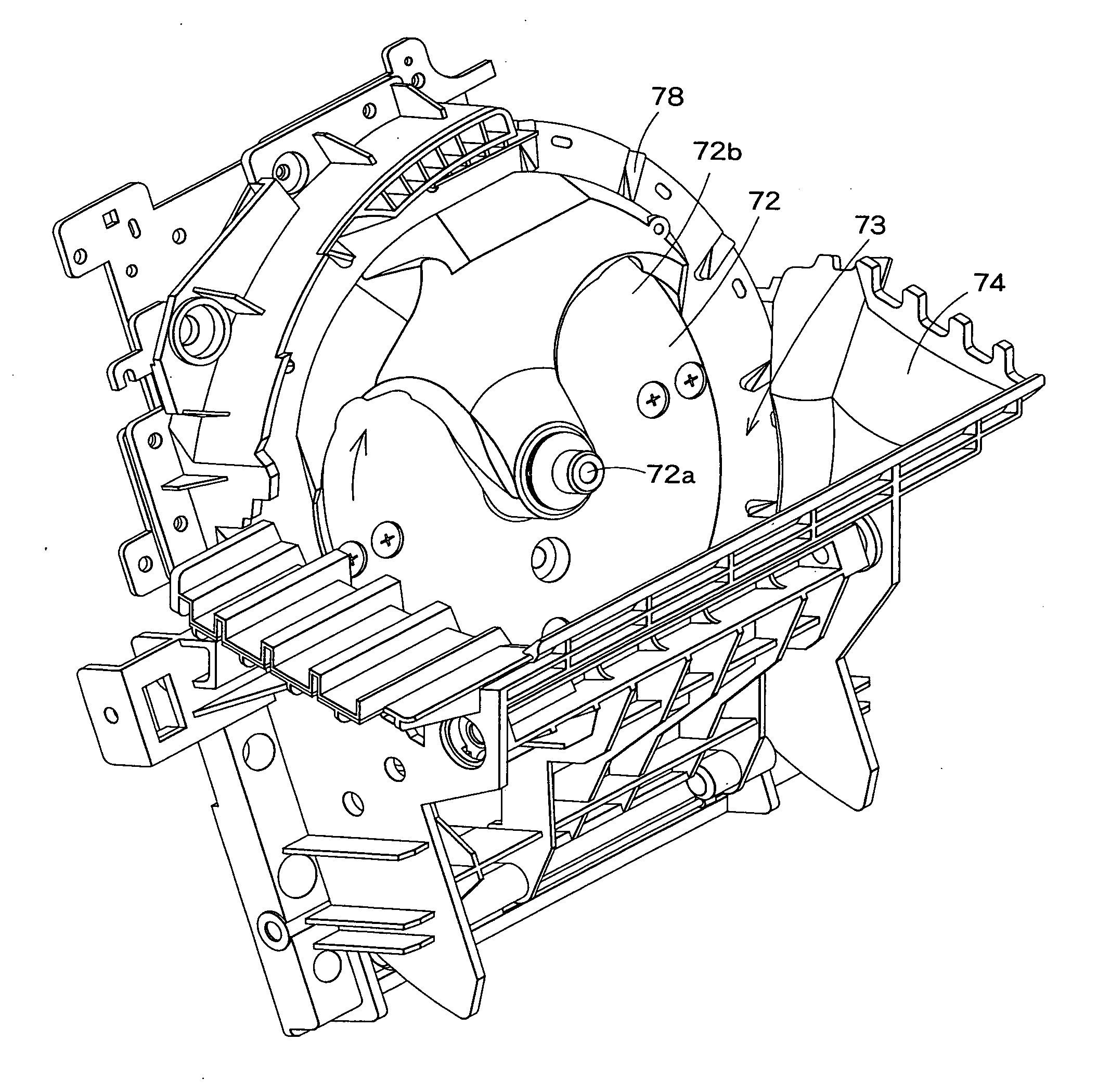
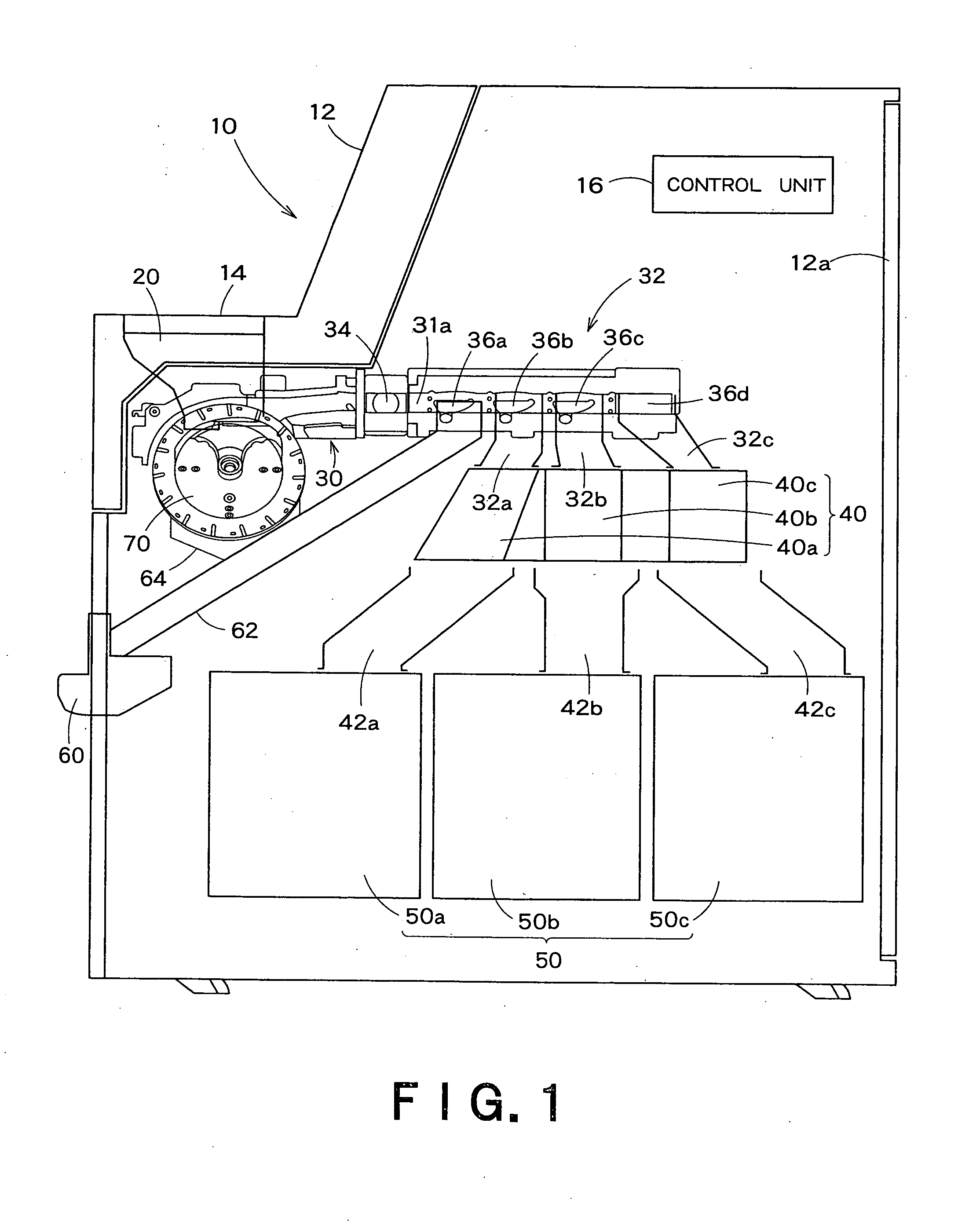
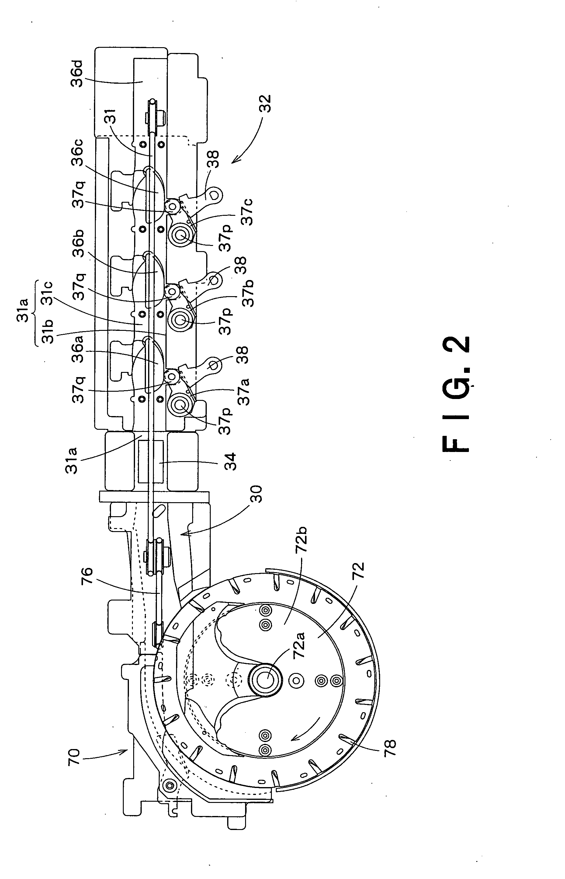
[0041]An embodiment of the present invention will be described herebelow with reference to the drawings. FIGS. 1 to 11 show a coin handling machine in this embodiment. FIG. 1 is a structural view schematically showing an inner structure of the coin handling machine in this embodiment. FIG. 2 is a structural view showing details of structures of a coin feeding unit, a transport unit and a sort unit in the coin handling machine shown in FIG. 1. FIG. 3 is a perspective view showing details of a structure of the coin feeding unit in the coin handling machine shown in FIG. 1. FIG. 4A is a side view of the coin feeding unit shown in FIG. 3, in which a hopper member is closed so that a coin storage space is defined between the hopper member and a surface of a rotary disc. FIG. 4B is a side view of the coin feeding unit shown in FIG. 3, in which the hopper member is opened. FIGS. 5 to 11 are views showing details of the structure of the coin feeding unit.

[0042]As shown in FIG. 1, the coin h...


PUM


Abstract

A coin feeding device (70) includes: a rotary disc (72) that is inclined at a predetermined angle with respect to a vertical direction; a hopper member (74) configured to define a coin storage space (73) for storing coins between the hopper member (74) and a surface (72b) of the rotary disc (72); and a plurality of protruding members (78) disposed on the surface (72b) of the rotary disc (72). Coins in a lower area of the rotary disc (72) are transported by the respective protruding members (78) to an upper area of the rotary disc (72) along with a rotation of the rotary disc (72). A first guide member (80) is located nearer to a center of the rotary disc than the respective protruding members on the rotary disc (72), with a slight gap being defined between the first guide member and the surface (72b) of the rotary disc (72). The first guide member (80) is configured to guide, in the upper area of the rotary disc (72), the coins transported by the respective protruding members (78), to a coin transport mechanism (76).

Description

FIELD OF THE INVENTION[0001]The present invention relates to a coin feeding device that stores coins put thereinto from outside and feeds the stored coins, and to a coin handling machine including the coin feeding device. In particular, the present invention relates to a coin feeding device capable of stably feeding normal coins one by one from a coin storage space, even when a rotary disc is rotated at a high speed so as to increase a processing speed of the coins, and to a coin handling machine including the coin feeding device.BACKGROUND OF THE INVENTION[0002]It has been conventionally known that a coin feeding device, which stores coins put thereinto from outside and feeds the stored coins, is installed inside a coin handling machine (see, JP8-212407A and JP8-212408A, for example). FIG. 12 is a front view showing the structure of a coin feeding device disclosed in JP8-212407A and JP8-212408A.[0003]The coin feeding device 90 disclosed in JP8-212407A and JP8-212408A includes: a ro...

Claims


Application Information

Patent Timeline
Patent Type & Authority Applications(United States)
IPC IPC(8): G07D1/00
CPCG07D9/008G07D3/125
Inventor TANAKA, MITSUO
Owner GLORY KOGYO KK
Learn More