
Intervertebral implant and installation tool

a technology of intervertebral implants and tools, applied in the field of medical devices, can solve the problems of high cost, intervertebral implants and techniques are associated with another disadvantage, and the vertebrae and associated connective elements are subject to injuries, so as to increase the height of the implant, enhance the shock absorption capability, and increase the implant height

Inactive Publication Date: 2011-06-02
INTERVENTIONAL SPINE
View PDF87 Cites 189 Cited by
  • Summary
  • Abstract
  • Description
  • Claims
  • Application Information

AI Technical Summary

Benefits of technology

[0017]Therefore, in accordance with at least one of the embodiments disclosed herein, there is provided an implant for use of intervertebral endoscope that overcomes the aforementioned drawbacks. For example, the implant can even be adjustable in height once installed, which allows the implant to be extracted or adjusted in the event of incorrect placement. Further, in some embodiments, the implant can allow for a degree of elasticity in the minimum separation of vertebrae.
[0042]In other embodiments, the implant can comprise a confinement casing. The confinement casing can comprise a channel, a lid, and a compartment extending intermediate the channel and the lid. The channel can be configured to receive at least a portion of the ram member therein. The compartment can be at least partially defined by a pair of sidewalls extending intermediate the lid and an end of the channel. The compartment can be configured to at least partially receive the body portions therein. The confinement casing can be configured to align the body portions in a vertical direction and prevent movement of the expansion component in a direction transverse to a longitudinal axis of the implant.

Problems solved by technology

Additionally, the vertebrae and associated connective elements are subject to injuries, including fractures and torn ligaments and surgical manipulations, including laminectomies.
Furthermore, notwithstanding the variety of efforts in the prior art described above, these intervertebral implants and techniques are associated with another disadvantage.
In particular, these techniques typically involve an open surgical procedure, which results higher cost, lengthy in-patient hospital stays and the pain associated with open procedures.
While using minimally invasive procedures to deploy an intervertebral prostheses is generally advantageous, such procedures do have the disadvantages of generally requiring the device to be passed through a relatively small diameter passage or tube.
In this regard, according to at least one of the embodiments disclosed herein is the realization that the deployed implant is completely rigid, which is unnatural and affects the comfort of the patient's movements.
In addition, many prior art intervertebral prostheses are not adjustable in height.
In other words, a surgeon cannot precisely set the spacing between vertebrae secured by the implant.
Furthermore, after deploying the implant, extraction or positional adjustments using an minimally invasive procedures are potentially dangerous and can damage the tissue of the patient.
These disadvantages can cause neuritis, among other complications.
Nevertheless, it is generally common for a surgeon to have to relocate or remove the implant because the surgeon often has no means of knowing exactly where the implant is located.

Method used


Image

  • Intervertebral implant and installation tool
  • Intervertebral implant and installation tool
  • Intervertebral implant and installation tool

Examples


Embodiment Construction

[0102]In accordance with certain embodiments disclosed herein, an improved intervertebral implant is provided that allows the clinician to insert the intervertebral implant through a minimally invasive procedure. For example, in one embodiment, one or more intervertebral implants can be inserted percutaneously to reduce trauma to the patient and thereby enhance recovery and improve overall results of the surgery. By minimally invasive, Applicant means a procedure performed percutaneously through an access device in contrast to a typically more invasive open surgical procedure. Such access devices typically provide an elongated passage that extends percutaneously through the patient to the target site. Examples of such access devices include, but are not limited to, endoscopes and the devices described in U.S. Patent Application Nos. 2006-0030872 and 2005-0256525 and U.S. Pat. Nos. 6,793,656 and 7,223,278, the entirety of these patent applications and patents are hereby incorporated ...


PUM


Abstract

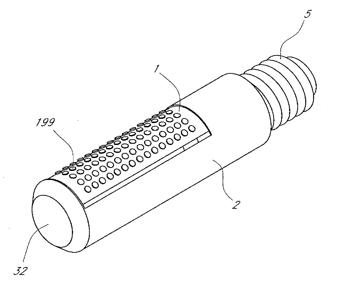
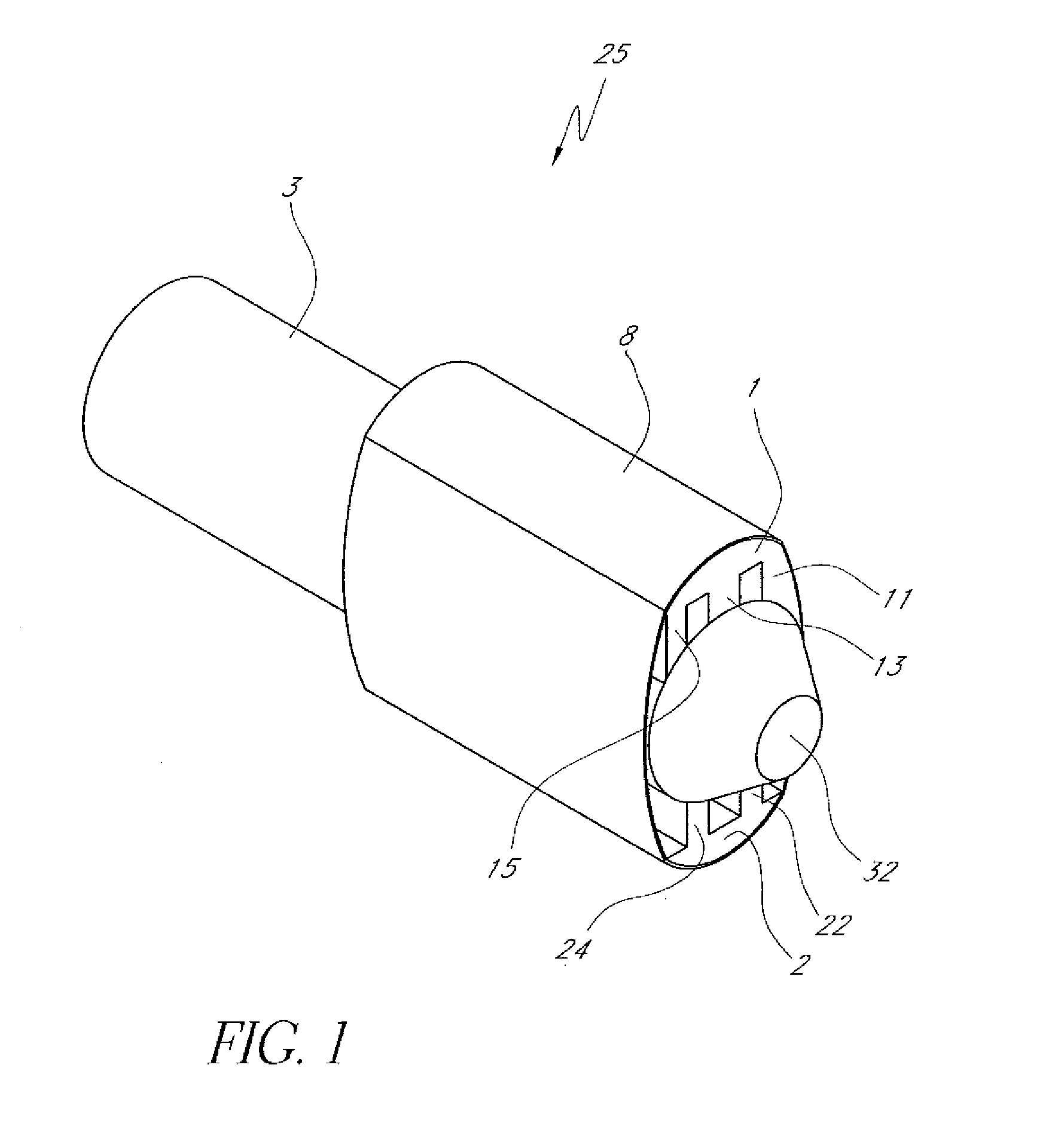
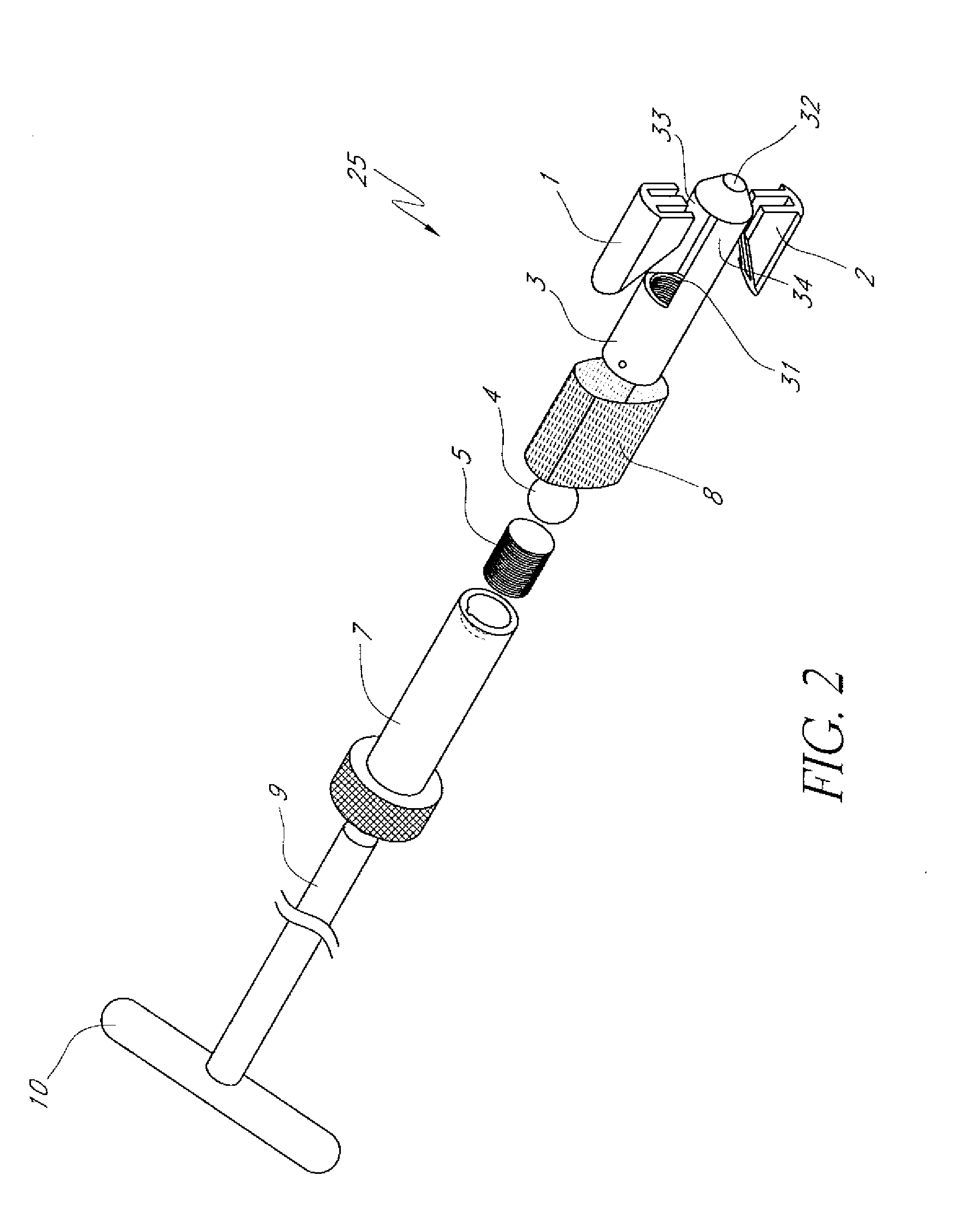
An intervertebral implant (25), an installation tool (500), and related methods are provided for ensuring a minimum distance between two vertebrae. The implant (25) can comprise a pair of opposing body portions (1, 2) and an expansion component. The expansion component can rotate relative to the body portions (1, 2) in order to urge a head portion (4) thereof against one or more inclined contact surfaces of at least one of the body portions (1, 2). In this manner, the body portions (1, 2) can be separated, thereby increasing a height of the implant (25). The installation tool (500) can comprise a plurality of components that can be moved relative to each other to facilitate expansion or contraction of the implant (25).

Description

CROSS-REFERENCE TO RELATED APPLICATIONS[0001]This application claims priority benefit under 35 U.S.C. §119(a) from Spanish Patent Application No. ES 200801551, filed May 26, 2008, and under 35 U.S.C. §119(e) from U.S. Provisional Application Ser. No. 61 / 176,460, filed on May 7, 2009, the entireties of the disclosures of each of which are hereby expressly incorporated herein by reference.BACKGROUND[0002]1. Field of the Inventions[0003]The present inventions relate to medical devices and, more particularly, to an intervertebral implant and an installation tool.[0004]2. Description of the Related Art[0005]The human spine is a flexible weight bearing column formed from a plurality of bones called vertebrae. There are thirty-three vertebrae, which can be grouped into one of five regions (cervical, thoracic, lumbar, sacral, and coccygeal). Moving down the spine, there are generally seven cervical vertebrae, twelve thoracic vertebrae, five lumbar vertebrae, five sacral vertebrae, and four ...

Claims


Application Information

Patent Timeline
Patent Type & Authority Applications(United States)
IPC IPC(8): A61F2/44A61B17/56
CPCA61F2/446A61F2310/00293A61F2002/30242A61F2002/30331A61F2002/30383A61F2002/30405A61F2002/30522A61F2002/3055A61F2002/30563A61F2002/30571A61F2002/30573A61F2002/30579A61F2002/30594A61F2002/30604A61F2002/30663A61F2002/443A61F2002/4627A61F2002/4629A61F2220/0025A61F2220/0033A61F2230/0071A61F2250/0007A61F2310/00023A61F2/4611A61F2/4425A61F2/4465
Inventor MORGENSTERN LOPEZ, RUDOLF
Owner INTERVENTIONAL SPINE
Learn More