
Shear reducing mattress cover

a mattress cover and shear force technology, applied in the field of mattress covers, can solve the problems of ulcers, ulcers or pressure sores, decubitus ulcers, etc., and achieve the effect of reducing the shear for

Active Publication Date: 2011-06-09
SPAN-AMERICA MEDICAL SYSTEMS
View PDF4 Cites 2 Cited by
  • Summary
  • Abstract
  • Description
  • Claims
  • Application Information

AI Technical Summary

Benefits of technology

[0008]In view of the recognized features encountered in the prior art and addressed by the present subject matter, improved apparatus and methodology have been provided for a mattress cover that reduces shear forces exerted on areas of a patient's body.
[0009]Accordingly, the present subject matter provides an improved mattress cover and corresponding support performance thereof for a patient. Further, the present subject matter in some embodiments relates to a unique mattress cover for redirecting shear on a patient's skin away from the areas of the body relatively more likely to develop decubitus ulcers.
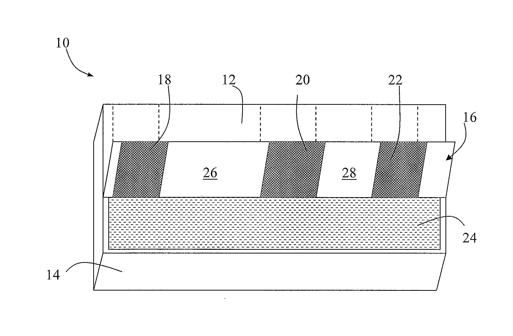
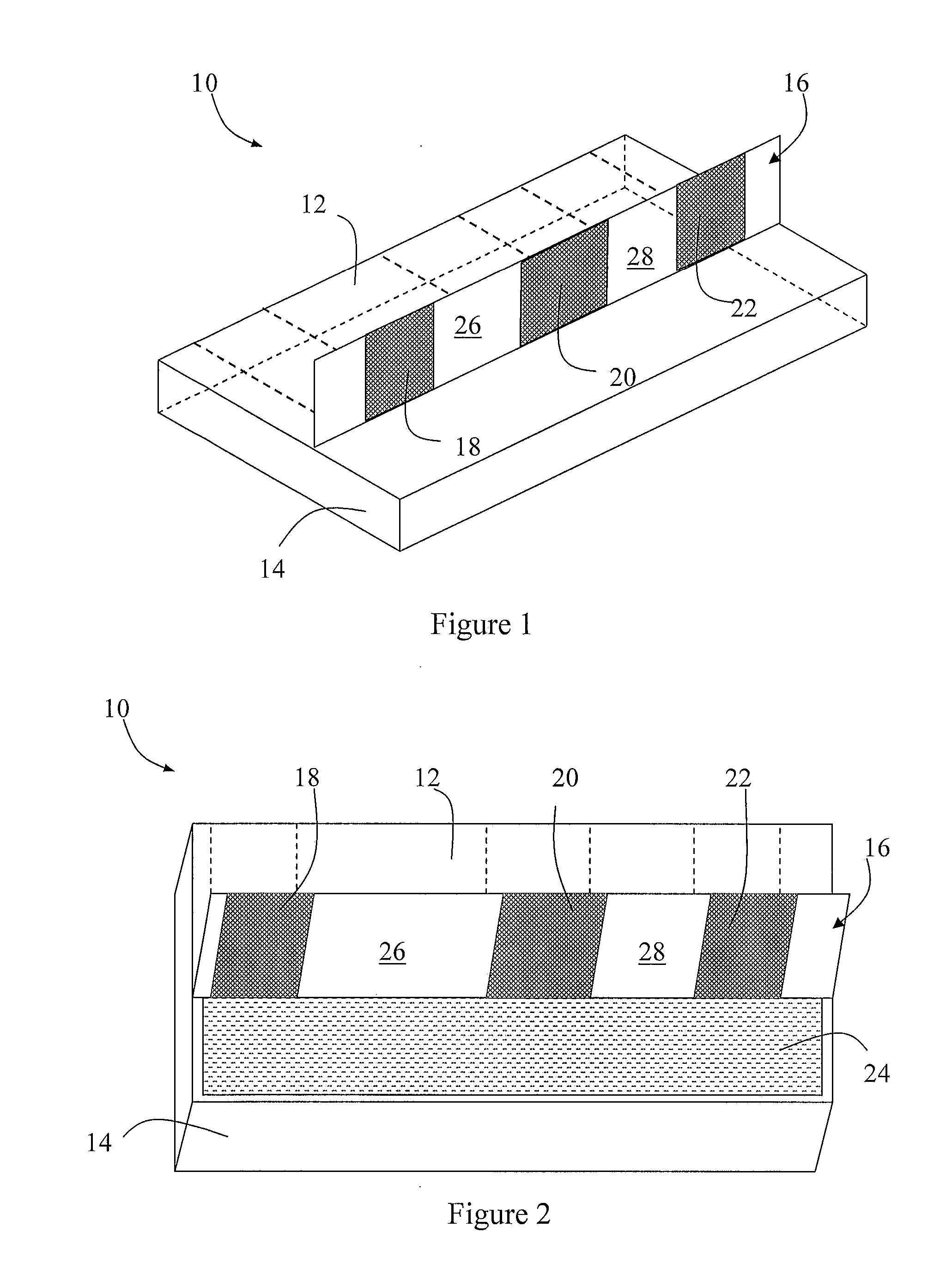
[0010]In certain present exemplary embodiments, a present mattress cover may include an upper portion designed to cover the topside of a mattress and at least one shear transfer zone attached to an underside of the upper portion of such present exemplary mattress cover. The shear transfer zone or zones may be made of a low shear material so as to create a low friction interface between the mattress and the mattress cover to reduce shear forces exerted by the mattress. Additionally, the shear transfer zone(s) in some embodiments thereof may be arranged such that a large portion of the shear forces exerted by the mattress can be redirected to areas of the body that are relatively speaking less likely to develop decubitus ulcers.
[0018]Yet another present exemplary embodiment of the present subject matter relates to apparatus for redirecting shear on the skin of a patient supported on an associated mattress. Such exemplary preferably comprises a mattress cover for covering an associated mattress, and having an upper portion generally facing and making contact with the topside of the associated mattress; a plurality of shear transfer zones formed on an underside of such upper portion, comprising relatively low shear material arranged in at least three respective areas at least generally aligned with a supported patient's heel, the ischial, and shoulder blade areas, respectively, so as to create a low friction interface between the associated mattress and such mattress cover to reduce shear forces exerted by the associated mattress; and a plurality of shear support areas defined by such underside of such upper portion between adjacent of such shear transfer zones. In such present exemplary apparatus embodiment, preferably such shear support areas include at least an area corresponding for support of a patient's thigh area, so that shear forces exerted by the associated mattress are redistributed to areas of a patient's body that are relatively less likely to develop decubitus ulcers.

Problems solved by technology

For example, pressure exerted by a mattress on bony portions or projections of the body, such as the shoulder blades, the ischials, or the heels, can lead to the development of decubitus ulcers.
Specifically, the compression of tissues caused by the force of a bone against a surface, such as a mattress, can compromise blood circulation in the compressed tissue, which can result in an ulcer or pressure sore.
Even if the amount of sliding is minimal, shear forces exerted by the mattress can lead to ulcers and a variety of other skin-related issues.
Additionally, such shear layers may also cause the mattress cover to bunch up as the patient slides down the mattress, which can further prevent sliding of the mattress cover relative to the shear layer and actually increase the amount of shear forces exerted on a patient's skin.

Method used


Image

  • Shear reducing mattress cover
  • Shear reducing mattress cover

Examples


Embodiment Construction

[0034]Selected combinations of aspects of the presently disclosed subject matter correspond to a plurality of different embodiments of the present subject matter. It should be noted that each of the exemplary embodiments presented and discussed herein should not insinuate limitations of the present subject matter. Features or steps illustrated or described as part of one embodiment may be used in combination with aspects of another embodiment to yield yet further embodiments. Additionally, certain features may be interchanged with similar devices or features not expressly mentioned in order to perform the same or similar function or functions.

[0035]Referring to the drawings, FIGS. 1 and 2 illustrate a presently exemplary preferred embodiment of a mattress cover generally 10. As shown, such mattress cover 10 may be understood as including an upper portion 12 and a bottom portion 14. The upper portion 12 includes an underside 16 that generally faces and makes contact with the topside ...


PUM


Abstract

A mattress cover is disclosed for redirecting shear on a patient's skin away from the areas of the body relatively more likely to develop decubitus ulcers. The mattress cover includes an upper portion designed to cover the topside of a mattress, and at least one shear transfer zone attached to an underside of the upper portion of the mattress cover. The shear transfer zone(s) may be made of a low shear material so as to create a low friction interface between the mattress and the mattress cover to reduce shear forces exerted by the mattress. Additionally, the shear transfer zone(s) may be arranged such that a large portion of the shear forces exerted by the mattress can be redirected to areas of the body that are relatively less likely to develop decubitus ulcers.

Description

PRIORITY CLAIM[0001]This application claims the benefit of previously filed U.S. Provisional Patent Application entitled “SHEAR REDUCING MATTRESS COVER,” assigned U.S. Ser. No. 61 / 285,070, filed Dec. 9, 2009, and which is incorporated herein by reference for all purposes.FIELD OF THE INVENTION[0002]The present subject matter relates generally to reducing shear forces in a bed. More particularly, the present subject matter relates to a mattress cover for reducing shear exerted on a bedridden patient to decrease the likelihood of the patient developing adverse conditions, such as decubitus or pressure ulcers.BACKGROUND OF THE INVENTION[0003]Decubitus or pressure ulcers, generally known as bedsores, are common for patients who are paralyzed or otherwise bedridden for extended periods of time. They can result from numerous factors. For example, pressure exerted by a mattress on bony portions or projections of the body, such as the shoulder blades, the ischials, or the heels, can lead to...

Claims


Application Information

Patent Timeline
Patent Type & Authority Applications(United States)
IPC IPC(8): A47C31/00
CPCA61G7/057Y10S5/944A47C27/002A61G2203/74
Inventor O'REAGAN, JAMES R.RABURN, RICHARD W.
Owner SPAN-AMERICA MEDICAL SYSTEMS
Learn More