Eureka AIR delivers breakthrough ideas for toughest innovation challenges, trusted by R&D personnel around the world.

Liquid air method and apparatus

a liquid air and method technology, applied in the direction of indirect heat exchangers, lighting and heating apparatus, machines/engines, etc., can solve the problems of increasing mismatch between electricity supply and demand, compromising the stability of the grid,

Inactive Publication Date: 2011-06-09
PRAXAIR TECH INC
View PDF9 Cites 43 Cited by
  • Summary
  • Abstract
  • Description
  • Claims
  • Application Information

AI Technical Summary

Benefits of technology

The present invention provides a method for storing and recovering energy from liquid air. The method involves compressing the air and pumping it through a regenerator to cool it and produce a high-pressure air stream. The high-pressure air stream is then expanded and introduced into a phase separator to produce a liquid phase and a vapor phase. The vapor phase is indirectly exchanged heat with the air cooling in the regenerator and the liquid air stream is introduced into a storage tank. The invention also provides a method for compressing the air and introducing it into a combustor to produce a flue gas stream that can be expanded in a second expander to produce a second exhaust stream that can be introduced into the regenerator to heat the air. The invention also provides a method for purifying the air by removing higher boiling contaminants.

Problems solved by technology

Due to the instantaneous variations in consumption and generation and the corresponding mismatch between them, the grid needs to include means of storing energy during periods of oversupply, and redeploy it during period of over demand.
Due to an increase of non dispatchable generation sources, the mismatch between electricity supply and demand has been growing in the last few years, and it is poised to reach levels that could compromise the stability of the grid.

Method used


Image

  • Liquid air method and apparatus
  • Liquid air method and apparatus
  • Liquid air method and apparatus

Examples


Embodiment Construction

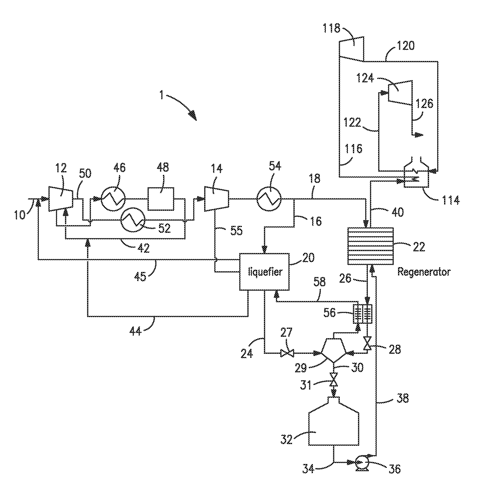
[0030]With reference to FIG. 1, an apparatus 1 is illustrated for liquefying air contained in a feed air stream 10 and thereafter, extracting energy from the liquid air that can be applied for the production of electrical power. Briefly, apparatus 1 is designed to operate in two phases, namely, a liquid air storage phase and an energy recovery phase.

[0031]During the liquid air storage phase, feed air stream 10 is compressed within a feed compressor 12 and optionally, a recycle compressor 14 and then divided into a first subsidiary compressed stream 16 and a second subsidiary compressed stream 18. Part of the refrigeration requirement for liquefying the air is provided by a liquefier 20 and a regenerator 22 in which refrigeration has been previously stored during the energy recovery phase. In the embodiment of the present invention illustrated in FIG. 1, this is done by passing the first subsidiary compress stream 16 into a liquefier 20 and the second subsidiary stream into the regen...


PUM


Abstract

A method and apparatus in which air is liquefied and stored for later energy recovery during which the liquid air is pumped to high pressure, heated and then expanded to recover the energy. During the recovery of energy, the pumped liquid air is heated within a regenerator that stores the refrigeration within the liquid air. During the liquefaction of the air, part of the refrigeration required is obtained from the refrigeration stored in the regenerator.

Description

RELATED APPLICATIONS[0001]This application is a utility application of provisional application Ser. No. 61 / 266,347, filed Dec. 3, 2009.FIELD OF THE INVENTION[0002]The present invention relates to a method and apparatus in which air is liquefied and stored for later energy recovery during which the liquid air is pumped to high pressure, heated and then expanded to recover the energy, with possible multiple expansions and reheat between expansions. More particularly, the present invention relates to such a method and apparatus that employs an integrated liquefier-regenerator system in which part of the refrigeration for a liquefier, used in liquefying the air, is provided by a regenerator that stores refrigeration imparted to the regenerator during the heating of the pumped and pressurized air.BACKGROUND[0003]The electric grid is in place to connect and balance electric generation and consumption. Due to the instantaneous variations in consumption and generation and the corresponding ...

Claims


Application Information

Patent Timeline
Patent Type & Authority Applications(United States)
IPC IPC(8): F25J1/02F28D17/00F28D17/02
CPCF02C6/10Y02E60/145F25J1/0012F25J1/0037F25J1/004F25J1/0045F25J1/0202F25J1/0242F25J1/0251F25J1/0284F25J2205/24F25J2205/66F25J2210/06F25J2220/02F25J2230/22F25J2235/02F25J2240/80F25J2240/82F25J2240/90F25J2270/06F28D20/021F02C6/14F25J2230/20F25J2245/40F25J1/0228Y02E60/14
Inventor GATTI, MARCO FRANCESCOBILLINGHAM, JOHN FREDRICROYAL, JOHN HENRIBONAQUIST, DANTE PATRICKWATT, MATHEW ROY
Owner PRAXAIR TECH INC
Why Eureka
Eureka Blog
Learn More