
Animal Cage And Method Of Assembly Thereof

a technology for enclosures and cages, applied in the field of enclosure assembly, can solve the problems of requiring more than one person to complete the assembly, requiring more than one person to provide tools or correct, and most cages are difficult for a layperson to assemble and setup, and achieve the effect of less cost and cheaper manufacturing and selling

Active Publication Date: 2011-06-09
MID WEST METAL PRODS
View PDF16 Cites 8 Cited by
  • Summary
  • Abstract
  • Description
  • Claims
  • Application Information

AI Technical Summary

Benefits of technology

[0011]One advantage of the above-mentioned embodiments is that no fasteners or tools are required for assembly. This provides convenience when assembling the enclosure assembly and avoids the inconvenience commonly encountered when an assembly is missing one or more tools or fasteners. Also, for those who do not have tools such as a hammer or screwdriver, embodiments of the present invention do not require any tools. Consumers therefore do not have to purchase new tools, nor do they have to search for used tools or suitable replacements. Also, the assembly process can be easily completed by a single person.

Problems solved by technology

Unfortunately, most cages can be difficult for a layperson to assemble and setup.
When purchased, these cages may not provide the tools or correct number of fasteners for assembling the cage, and even when the tools and correct number of fasteners are provided, assembly often requires more than one person to complete.
This can be inconvenient to the pet owner who wants an easy-to-assemble cage that requires minimal time and effort for assembling the cage.
Additional inconvenience is found when the owner does not have the requisite tools or fasteners for assembling the cage.
In such a circumstance, the owner must purchase the proper tools and fasteners which ultimately increases the cost of the cage.

Method used


Image

  • Animal Cage And Method Of Assembly Thereof
  • Animal Cage And Method Of Assembly Thereof
  • Animal Cage And Method Of Assembly Thereof

Examples


Embodiment Construction

[0036]The embodiments of the present invention described below are not intended to be exhaustive or to limit the invention to the precise forms disclosed in the following detailed description. Rather, the embodiments are chosen and described so that others skilled in the art may appreciate and understand the principles and practices of the present invention.

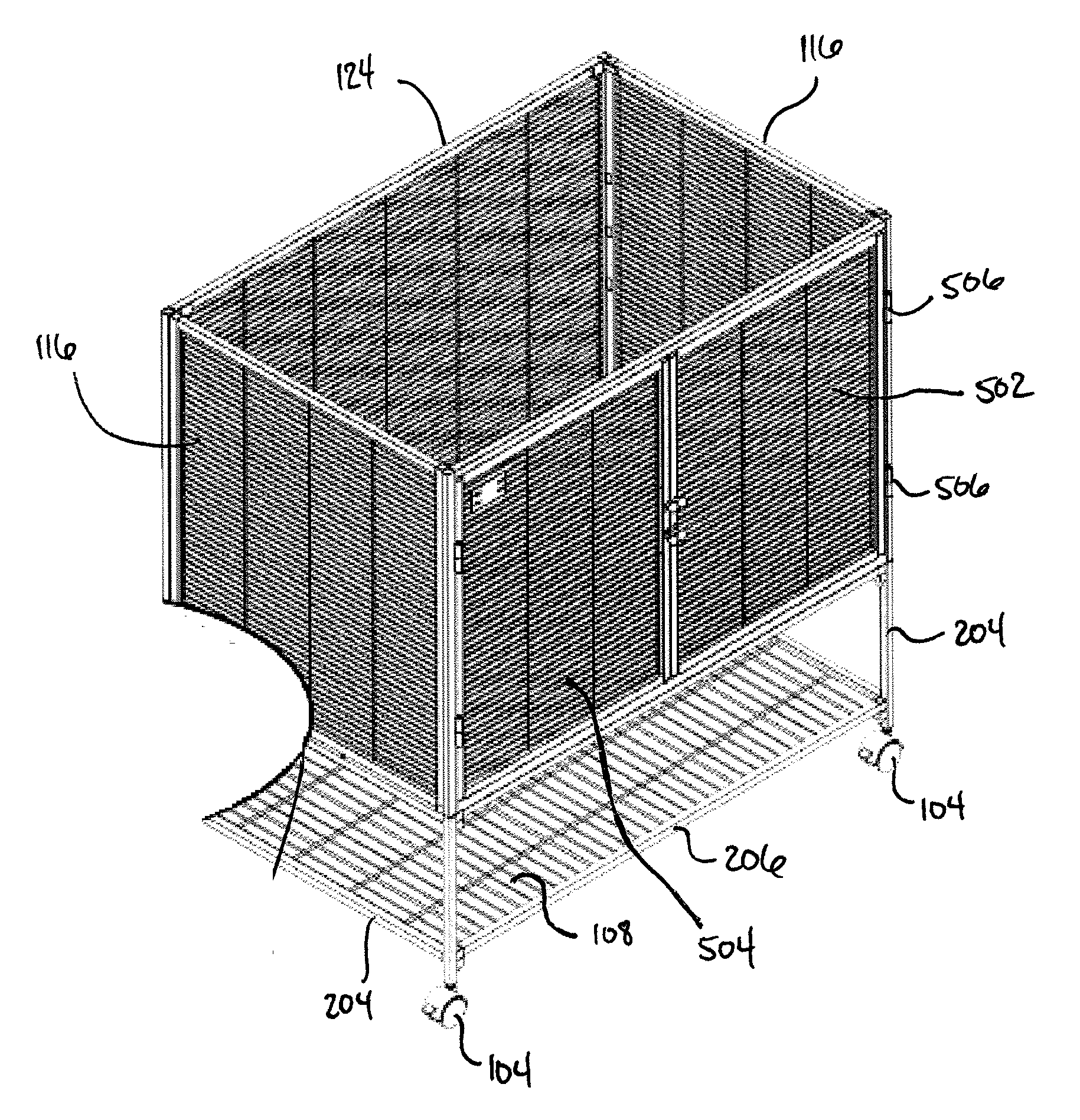
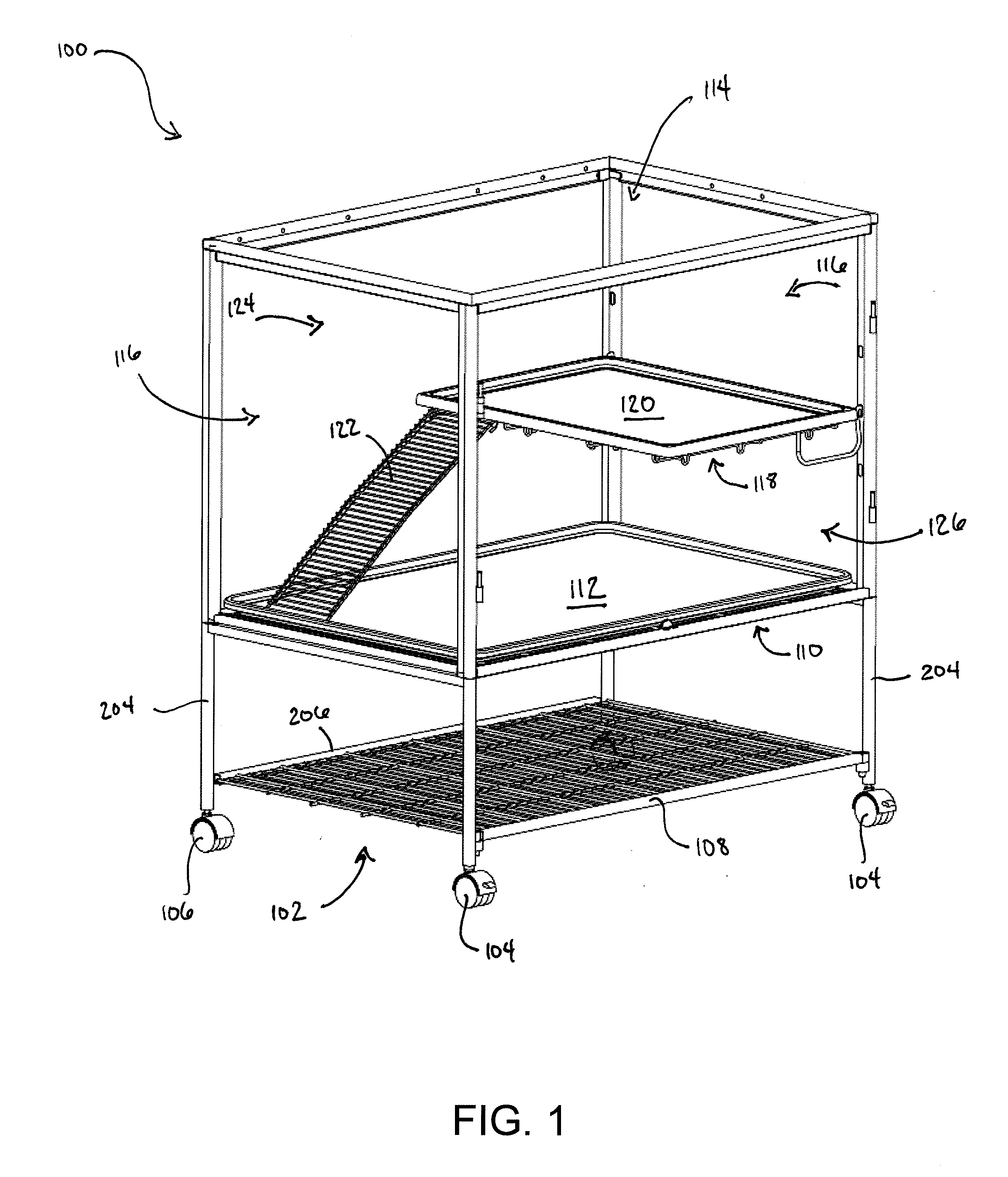
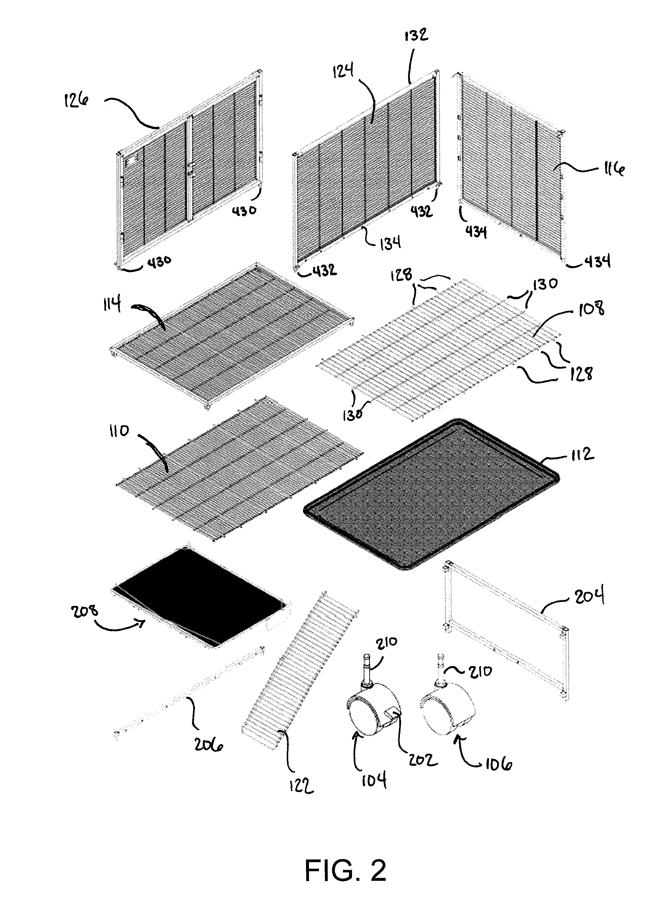
[0037]With reference to FIGS. 1 and 2, an exemplary embodiment of an enclosure assembly 100 is shown. In this embodiment, the enclosure assembly 100 includes a base 102, a top wall 114, a back wall 124, a pair of side walls 116, and a door assembly 126. The top wall 114, back wall 124, side walls 116, and door assembly 126 can be made of a steel wire mesh; however, the wire mesh is removed in FIG. 1 so that the interior of the enclosure assembly 100 can be seen more easily. In other embodiments, the different walls can be made from aluminum, plastic, or other material known to one skilled in the art.

[0038]In the case of the steel...


PUM

PropertyMeasurementUnit
durableaaaaaaaaaa
timeaaaaaaaaaa
coloraaaaaaaaaa

Abstract

The present invention relates to a method of forming an enclosure assembly without using tools or fasteners to complete the assembly. The method includes forming a base from a side support, front support, and a plurality of casters. A door assembly and back wall are coupled to the base by aligning a plurality of pegs therefrom with corresponding openings defined in the base. A plurality of protruding wires of a bottom wall are aligned and inserted into corresponding openings defined in the door assembly and back wall. In addition, a plurality of pegs that protrude from a side wall are inserted into a plurality of corresponding openings defined in the door assembly and back wall such that the side wall couples to the door assembly and back wall. The method also includes coupling a top wall to the door assembly, side wall, and back wall. A shelf assembly can be coupled to the side wall and / or back wall, and a ramp can be pivotably coupled to the shelf assembly.

Description

BACKGROUND[0001]The present invention relates to an enclosure assembly, and more particularly to an enclosure assembly useful for containing animals which requires no tools or fasteners for assembly.[0002]Animal cages and the like are very popular for pet owners to purchase for housing their domestic pet. The cage can allow the pet owner to enjoy their pet while also maintaining the pet in an enclosed and controlled environment. Cages or other similar enclosures can be made from a variety of materials such as plastic, iron, steel, wood, aluminum, woven fabric, etc. The material from which the cage is made can depend on whether the cage is primarily used indoors or outdoors. In any event, pet owners want cages to be durable so that animals enclosed within the cage cannot escape and animals outside the cage cannot enter.[0003]Cages also can include multiple functions in addition to providing a safe enclosure for the pet. For example, the cage can provide a sanitary environment for the...

Claims


Application Information

Patent Timeline
Patent Type & Authority Applications(United States)
IPC IPC(8): A01K1/03B23P11/00
CPCY10T29/49826A01K1/033
Inventor GREENE, MICHAEL E.JENNINGS, BRYAN W.JONES, TERRANCE L.CLEMMONS, DAVID L.
Owner MID WEST METAL PRODS
Learn More