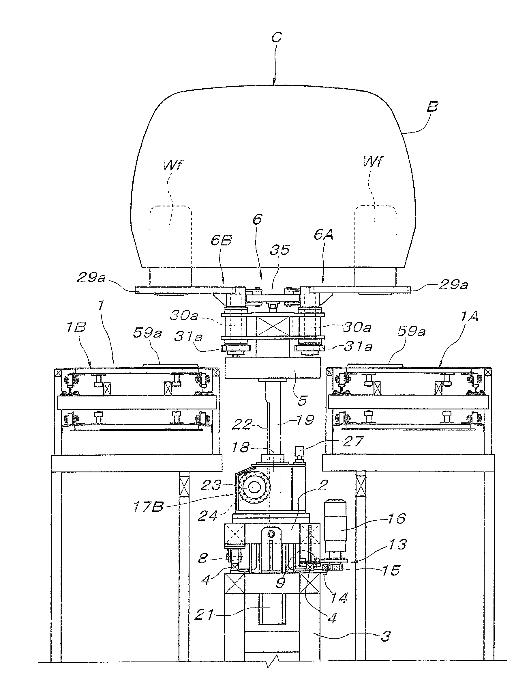
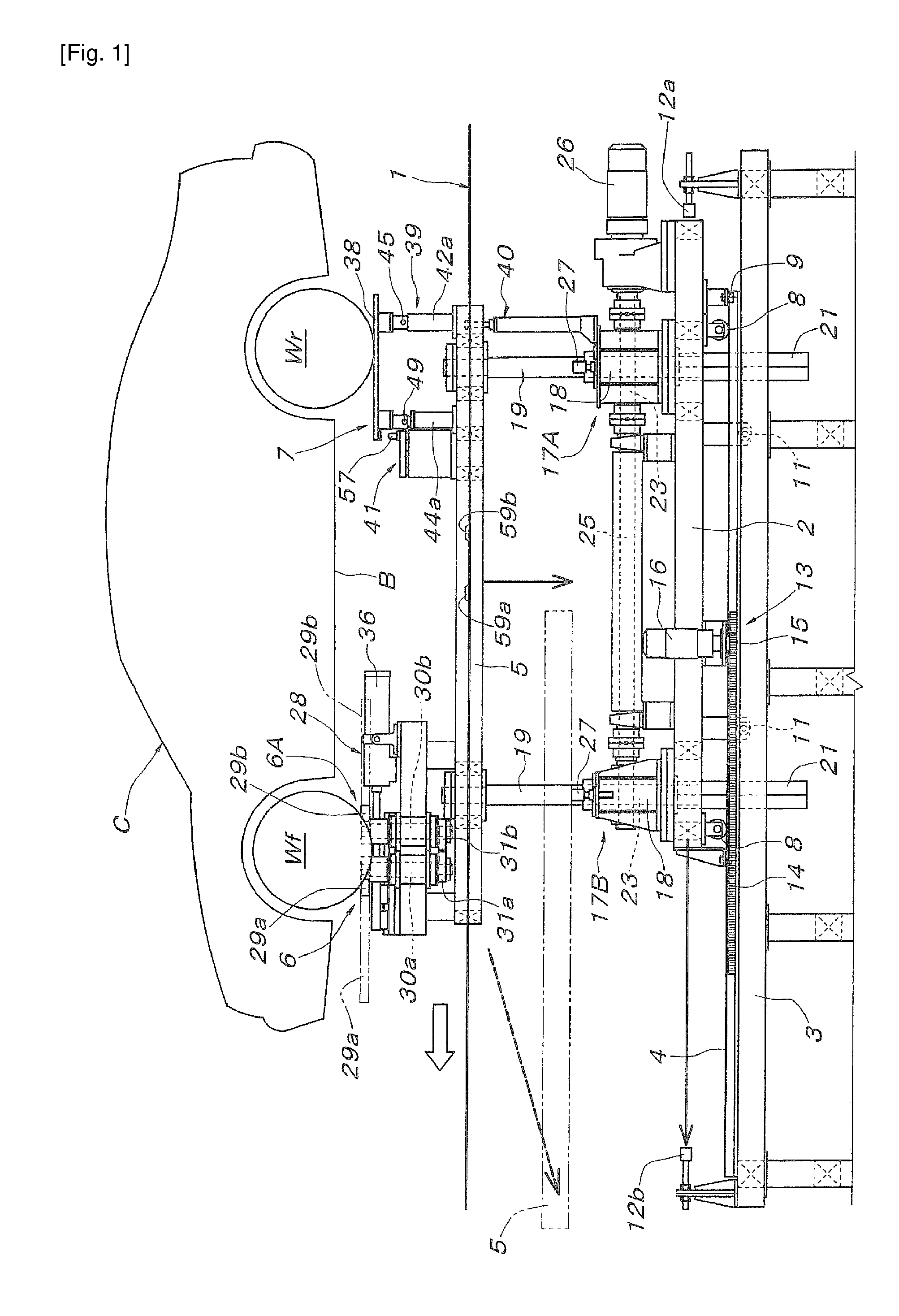
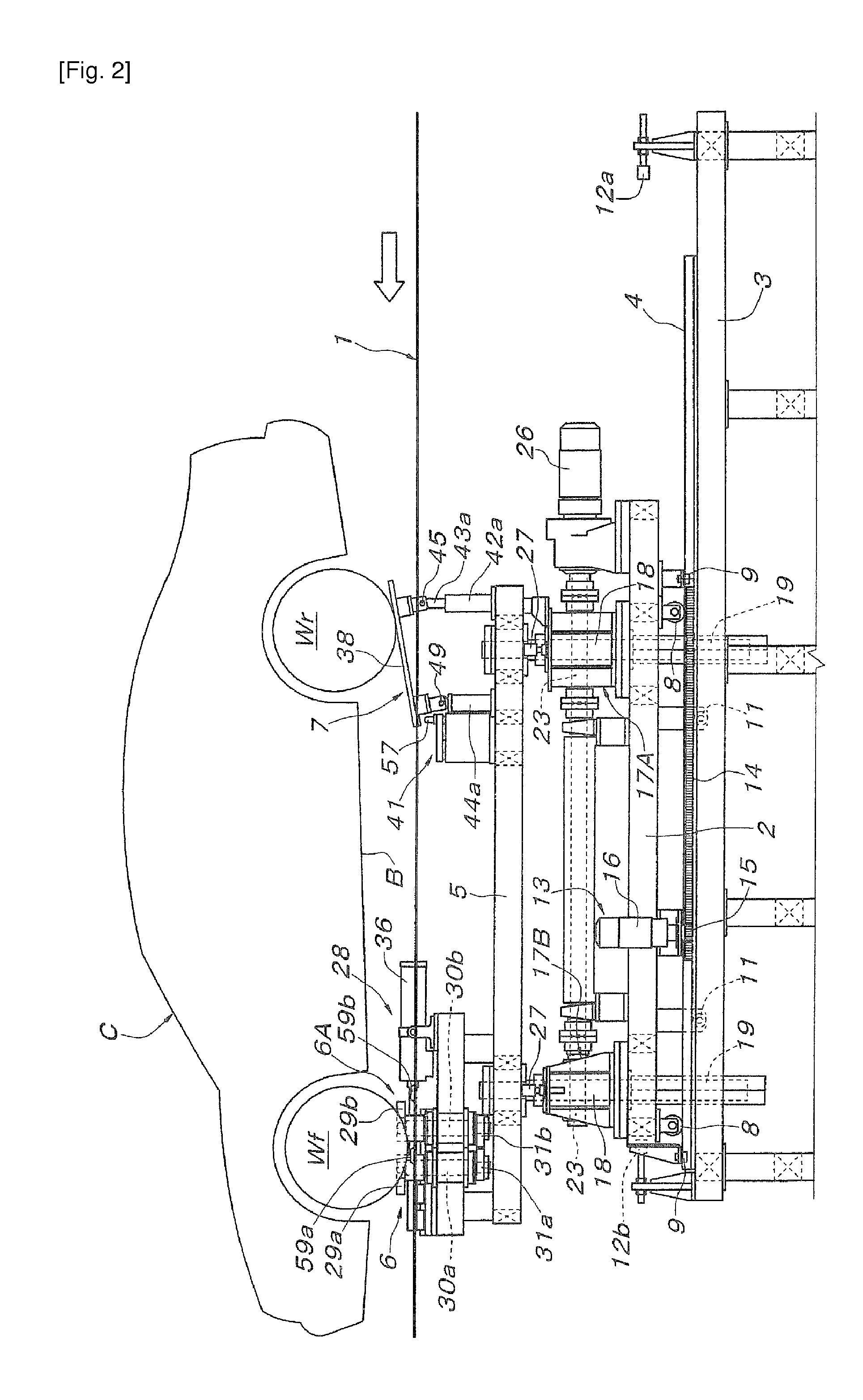
[0010]According to the apparatus for transferring vehicles onto a conveyor of the present invention as described in Claim 1, with the situation that front wheels and rear wheels of a vehicle are supported, respectively, by the front wheel supporting means and the rear wheel supporting means on the elevator at an elevated position, the front wheel supporting means and the rear wheel supporting means are lowered to the lowermost position close to the conveyor, while keeping the position, a pair of front and rear wheel supporting arms that can open and close either one of the front and rear wheel supporting means is opened from the closed posture for supporting the wheels to the opened posture to transfer the wheels supported by the pair of the front and rear wheel supporting arms onto the conveyor. At this moment, since the posture of the wheel supporting plate of the other wheel supporting means has been changed to the front-down tilted posture by the posture switching means, the wheels having been already transferred onto the conveyor are dragged by the conveyor to the convey direction and the wheels remaining on the wheel supporting plate can smoothly roll down to the convey direction to be transferred to the conveyor, assisted by the front-down inclination of the wheel supporting plate.
[0011]In other words, since only one wheel supporting means out of the front and rear wheel supporting means is constituted of a pair of front and rear wheel supporting arms that open and close horizontally and support wheels at a predetermined position, and the other wheel supporting means supports wheels on the wheel supporting plate without determining the position of the wheels in terms of the convey direction. Therefore, any vehicles having the distances between the front and rear wheels varying within the range of the width (length) of the wheel supporting plate in terms of the convey direction can be safely transferred onto the conveyor under the condition that the vehicles are surely positioned at a predetermined position with reference to the wheels supported by the pair of the front and rear wheel supporting arms in the closed posture.
[0012]Furthermore, since the wheel supporting plate is kept in the horizontal posture from the
receipt of vehicle at a predetermined height above the conveyor until the arrival thereof at the lowermost position where the vehicle is transferred onto the conveyor, the supported vehicle is not subjected to a driving force into the convey direction, as in the case of the support of the wheels by a wheel supporting plate inclined front-down from the beginning, and the vehicle can be lowered safely to be transferred onto the conveyor, even if the engagement depth of the wheels into the pair of the front and rear wheel supporting arms in the closed posture is shallow. Contrary, when vehicles should be transferred onto the conveyor by letting the wheels rolling down from the wheel supporting plate in the horizontal posture to the convey direction, a considerably strong driving force should be given to the vehicles through the wheels having been transferred to the conveyor earlier. Consequently, very low profiled wheel positioning bars placed on the conveyor so as to hold both the front and rear sides of the
ground contact patch of the wheels may not able to transfer the vehicle keeping it at a predetermined position of the conveyor, instead the bars may pass under the wheel due to the resistance in dragging out the wheels to the convey direction from the wheel supporting plate in the horizontal posture. In contrast, since the wheel supporting plate is tilted front-down at the stage of transferring the vehicle onto the conveyor giving a traveling force to the wheels on the wheel supporting plate in the direction for transferring it onto the conveyor, even with the very low-profiled wheel positioning bars provided on the conveyer, the vehicles on the conveyor are able to be surely carried, positioning the wheels at a predetermined position.
[0013]By the constitution according to Claim 2, compared to the case where elevators moving synchronized up and down are installed on both left and right sides of the conveyor, the structure of the whole apparatus can be simpler, and the present invention can be implemented simply and inexpensively.
[0014]Further, by the constitution according to Claim 3, compared to the constitution where vehicles are transferred onto the conveyor exactly below the vehicle receiving position above the conveyor, the next vehicle can be carried to the vehicle receiving position above the conveyor during the transportation of the vehicle received at the vehicle receiving position above the conveyor to a lower forward position, even if the vertical space between the vehicle receiving position above the conveyor and the conveyor is so small that the vehicle waiting at the vehicle receiving position above the conveyor could interfere with the vehicle being transferred onto the conveyor, thus the
cycle time for transferring vehicles onto the conveyor can be shortened.
[0015]Further, by the constitution according to Claim 4, it is not necessary to install an
actuator, such as a motor and a cylinder unit, for tilting the wheel supporting plate on the elevator or on the side where the elevator is supported, which makes the structure of the whole apparatus simpler compared to the case where installment of such
actuator is necessary, and the present invention can be implemented simply and inexpensively. In this connection, when the
front edge of the wheel supporting plate is driven vertically to change the posture, the supporting level of wheels on the wheel supporting plate in the horizontal posture becomes high, and therefore the vehicle is supposed to be lowered on to the conveyor while being supported in an inclined posture from the beginning. On the contrary, by the constitution according to Claim 4, since the wheel supporting plate is switched to the tilted posture by pushing up the rear edge thereof, the supported vehicle can be supported substantially horizontal until just before the transfer of the vehicle onto the conveyor, and the vertical conveyance of the supported vehicle down to the conveyor can be carried out safely.


