Pneumatic classification of mixtures of particulates

a technology of particulates and mixtures, applied in the direction of gas current separation, dispersed particle separation, separation processes, etc., can solve the problems of reducing the airflow velocity of the airstream, and reducing the aerodynamic support fraction. , the effect of reducing the velocity

Inactive Publication Date: 2011-06-09
MILLER RICHARD L
View PDF4 Cites 9 Cited by
  • Summary
  • Abstract
  • Description
  • Claims
  • Application Information

AI Technical Summary

Benefits of technology

[0032]In another embodiment, the present invention may be understood, as a process for pneumatic classification of a mixture of granular particulates into a low aerodynamic support fraction of particulates and a high aerodynamic support fraction of particulates. The process includes the steps of providing an apparatus, entraining, by vacuuming or otherwise dispensing the mixture of granular particulates into the airstream, transporting the entrained mixture of granular particulates into a chamber of the provided apparatus, and reducing velocity within the chamber thereby allowing the low aerodynamic support fraction to fall. More specifically, in the inventive process, the provided apparatus includes: an intake, a chamber, means for reducing velocity, a vacuum source and means for creating a vertical airflow. Even more specifically, the intake has a head at one end and an outlet at the other end. The chamber has a bottom, an inside, an outside, a chamber inlet, a chamber exhaust outlet, and a chamber discharge outlet. The chamber inlet is fluidly connected to the outlet end of the intake and disposed to receive an airstream from the intake and to direct at least a portion of the airstream from the intake into the chamber. The airstream, within the intake, is characterized by a capability of entraining the mixture of granular particulates which are to be classified. The chamber exhaust outlet is capable of discharging the airstream and the high aerodynamic support fraction particulates entrained within the airstream from the chamber. The chamber discharge outlet is located on the bottom of the chamber and is for discharging previously entrained, low aerodynamic support fraction particulates which have or are falling by gravity through and from the chamber. The means for reducing the velocity of the airstream within the chamber, preferably includes a pre-exhaust located proximate or near the chamber inlet. The pre-exhaust has a pre-exhaust inlet and a pre-exhaust outlet. Optionally, the pre-exhaust may be adjustable as to position and / or cross-section and / or airstream volume which may pass therethrough. Preferably, the vacuum source for producing vacuum is fluidly connected to the chamber exhaust outlet. Preferably, the pre-exhaust outlet is also fluidly connected to the vacuum source. Alternatively, the pre-exhaust outlet may be connected to another vacuum source, distinct from the vacuum source connected to the chamber exhaust outlet. When the airstream is drawn through the intake and into the chamber by vacuum applied to the chamber and thereby through the intake to the head end of the intake, a mixture of granular particulates is vacuumed into the intake at head end of the intake forming an airstream with an entrained mixture of granular particulates. The airstream with the entrained mixture of granular particulates is transported through the intake to the chamber and enters the chamber at the chamber inlet and the velocity of the airstream with the entrained mixture of granular particulates then slows or is reduced in velocity thereby allowing the low aerodynamic support fraction particulates to fall under gravity from the reduced velocity airstream to the chamber discharge outlet. The means for creating a vertical airflow in the chamber discharge outlet includes an air admittance means for providing vertical airflow countercurrent to falling low aerodynamic support fraction particulates so as to airwash remove any high aerodynamic support fraction particulates inadvertently falling with the low aerodynamic support fraction particulates into and through the chamber discharge outlet. Optionally, this vertically directed upward airflow, countercurrent to the falling particulates, is adjustable. In the process, one early step is entraining the mixture of granular particulates in the airstream. This may be by vacuuming the mixture of granular particulates into the head end of the intake to entrain the mixture of granular particulates. Alternatively, the mixture of granular particulates may be dispensed into the airstream to entrain the mixture of granular particulates. The entrained mixture of granular particulates is transported through the intake and into the chamber. The velocity of the airstream bearing the entrained mixed particles is reduced within the chamber thereby allowing the low aerodynamic support fraction particulates to fall under gravity to the chamber discharge outlet. Meanwhile, the high aerodynamic support fraction particulates exit the chamber through the chamber exhaust outlet. The process can be applied to a broad range of mixtures. More specifically, the process is applicable where the mixture of granular particulates is selected from the group of mixtures of granular particulates consisting of: landscape rock, dirt and debris; almonds and orchard trash, sticks, dirt, leaves; plastic pellets and fines and tails; coarse sand and fine sand; sand and tailing materials, fines and dust; blast media and paint chips, rust, and dust; coarse blasting media and fine blasting media; railroad ballast, fractured ballast, dirt and debris; lead pellets and dirt and debris; lead bullets and backstop material and dirt and debris; glass and shredded paper; dense ore minerals and pea gravel and dirt; shot media and worn shot media and dust; and agricultural grain / seed / soy beans and chaff, stems and weed seed.

Problems solved by technology

Most forms of decorative ground cover deteriorate over time.
Mulch decays, fades, and gets carried away by wind, water, animal foraging, and foot traffic.
Decorative rock is stable and lasts for years, but it is also prone to losing its aesthetic qualities.
In arid areas the buildup of airborne sand is a problem.
If located near roadways, there can be a problem with sand from snow removal.
Home owners have struggled to clean their landscape rock in a variety of ways including picking it up manually and cascading it over an improvised screening device while simultaneously hosing it off Such methods are cumbersome, tedious and involve handling the rock multiple times.
This is expensive and prone to causing damage to existing lawns and shrubbery.
Filtering Discharged Air” issued on Apr. 5, 1988 to Duncan Johnstone, the teachings of which are incorporated herein by reference in their entirety, as well as the industrial vacuum sold by Christianson Systems, Inc. of Blomkest, Minn. under the tradename “RockVac.” But, such vacuums do not clean the rock so it can be reused.
The old rock, along with accompanying dirt and debris, is often disposed of in landfills, thereby exacerbating a growing ecological problem.

Method used


Image

  • Pneumatic classification of mixtures of particulates
  • Pneumatic classification of mixtures of particulates
  • Pneumatic classification of mixtures of particulates

Examples


second embodiment

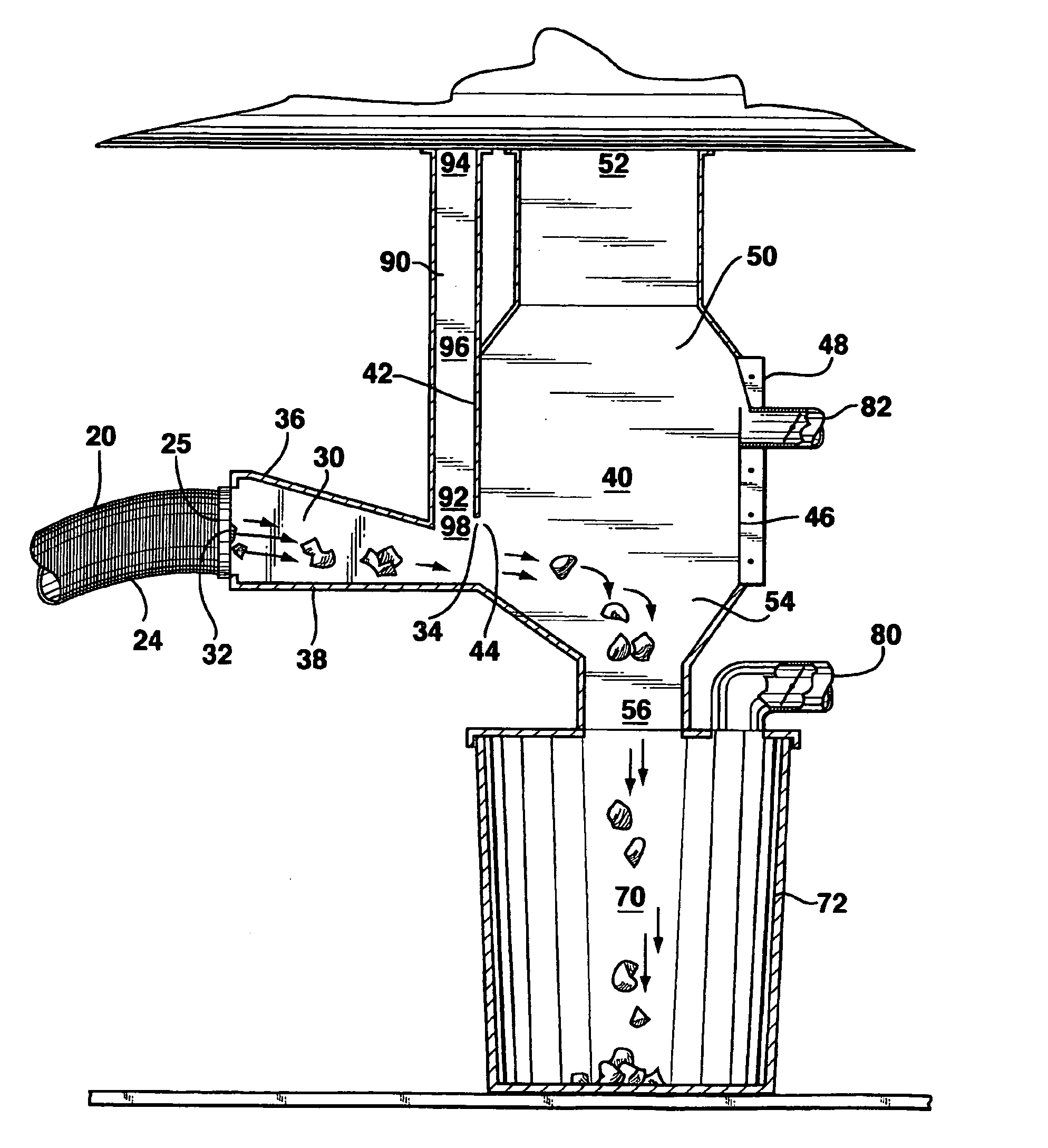
[0092]There are three other embodiments of the pre-exhaust 90 that do not require the chamber partition 58 to form the pre-exhaust 90. A second embodiment shown in FIG. 5, includes an entry section 30 with an entry section pre-exhaust outlet 98 connected to a pre-exhaust inlet 92 to abruptly withdraw air from the entry section 30 between the entry section inlet 32 and the entry section outlet 34. The pre-exhaust midsection 96 may be a structure separate from chamber 40 depending on the proximity of the entry section pre-exhaust outlet 98 to chamber 40.

[0093]A third embodiment shown in FIG. 6 is a special case of the second embodiment and includes the entry section pre-exhaust outlet 98 immediately adjacent to the entry section outlet 34 next to the chamber inlet side 42. Entry section pre-exhaust outlet 98 is connected to a pre-exhaust inlet 92 to abruptly withdraw an air steam from the entry section 30 proximate the chamber inlet side 42. The pre-exhaust midsection 96 may have a po...

fourth embodiment

[0094]The fourth embodiment, shown in FIG. 7, includes a chamber inlet side exhaust outlet 99 proximate the chamber inlet 44 and connected to the pre-exhaust inlet 92 for the abrupt withdrawal of air from the chamber 40 proximate the chamber inlet 44. The pre-exhaust midsection 96 can be adjacent to or separate from the chamber 40.

[0095]Now, turning to the other elements connected to the chamber 40, a chamber collector means 70 is disposed adjacent to and below the chamber discharge outlet 56. The chamber collector means 70 comprises a collection container 72 such as a common five gallon pail which is removable and has an airtight connection to the chamber discharge outlet 56 when the apparatus 10 is operating. Alternatively, the chamber collector means 70 may be one or more integral hoppers that discharge to other containers or onto a conveyer.

[0096]A chamber air supply means 80, FIGS. 3 and 4, draws ambient air into the chamber discharge outlet 56 through collection container 72 b...

embodiment 300

[0143]As depicted in the block diagram of FIG. 32, in another embodiment 300, the present invention is a method of separation of mixtures of populations of high specific gravity particles and low specific gravity particles into two segregated populations of granules. In the method of this embodiment, the two segregated populations of granules are each characterized by a dissimilar range of specific gravity. These two populations may be understood as defining, first, a high specific gravity range granular material and defining, second, a low specific gravity range granular material. The method for separating the two populations includes the steps of: providing an initial airstream 302; incorporating the mixed granular material into the initial airstream 304; slowing the initial airstream to allow the high specific gravity material to fall 306; providing a second airstream with an upward direction 308 and directing the second airstream against the falling high specific gravity materia...


PUM

PropertyMeasurementUnit
specific gravityaaaaaaaaaa
aerodynamic support fractionaaaaaaaaaa
gravityaaaaaaaaaa

Abstract

Process for pneumatic classification of mixture of granular particulates by providing an apparatus, entraining mixture, reducing velocity of entraining airstream, and airwashing falling particulates of low aerodynamic support. Specific applications include a method separating mixed granular material based upon dissimilar specific gravities, useful in cleaning firearm ranges by separating lead from backstop material. Falling granular lead particulates can also be airwashed and negative pressure facilitates control of lead dust. Also disclosed are applications that pick up and clean or enrich precious metal bearing ore, and a broad range of applications from heavy mixtures, such as landscape rock, to light mixtures such as grain.

Description

RELATED APPLICATIONS[0001]This application is a continuation-in-part of co-pending U.S. application Ser. No. 12 / 803,990 filed Jul. 12, 2010 which is a continuation-in-part of U.S. application Ser. No. 12 / 460,962 filed Jul. 13, 2009, now U.S. Pat. No. 7,867,323, which is a continuation of Ser. No. 11 / 644,167 filed Dec. 22, 2006, now U.S. Pat. No. 7,559,962, hereby incorporated by reference in its entirety and to which application priority is claimed under 35 U.S.C. §120. This application also claims priority, through the above-mentioned U.S. application Ser. No. 12 / 803,990, to U.S. provisional applications 61 / 270,750 and 61 / 270,758, both filed Jul. 13, 2009, and U.S. provisional application 61 / 338,308 filed Feb. 17, 2010, all three of which provisional applications are hereby incorporated by reference in their entirety herein.BACKGROUND OF THE INVENTION[0002]1. Field of the Invention[0003]The present invention is directed to a process for pneumatic classification of mixtures of parti...

Claims


Application Information

Patent Timeline
Patent Type & Authority Applications(United States)
IPC IPC(8): B07B4/02
CPCB07B7/01B07B4/04B07B11/06
Inventor MILLER, RICHARD L.
Owner MILLER RICHARD L
Why Eureka
Try Eureka