Laser machining and scribing systems and methods

a technology of scribing system and laser machining, which is applied in the field of laser machining, can solve the problems of narrower streets between the devices, insufficient image of the streets by the front camera, and other problems, and achieves the effect of reducing the number of devices

Inactive Publication Date: 2011-06-09
IPG PHOTONICS CORP
View PDF102 Cites 89 Cited by
  • Summary
  • Abstract
  • Description
  • Claims
  • Application Information

AI Technical Summary

Problems solved by technology

Positioning the devices more closely on the semiconductor wafer results in narrower streets between the devices.
In such a position, the front side camera often cannot image the streets sufficiently to provide alignment, particularly when the wafer includes an opaque coating or layer on the back side.
Back side scribing may also present other problems.
One way to assure crack propagation within the streets when back side scribing is to widen the streets, but this also reduces yield.
Another way to prevent the cracks from propagating beyond the streets is to provide deeper scribes, which is slower, requires more energy and may lead to damage from thermal transmission.
Accordingly, back side scribing and dual side scribing of semiconductor wafers presents significant alignment challenges because the camera located on the same side as the laser machining process often cannot adequately image a feature on an opposite side.
The air bearing X-Y positioning stages used in some existing laser machining systems to provide more accurate and precise positioning, however, prevent the use of a camera on the side of the workpiece opposite the laser machining process.

Method used


Image

  • Laser machining and scribing systems and methods
  • Laser machining and scribing systems and methods
  • Laser machining and scribing systems and methods

Examples


Embodiment Construction

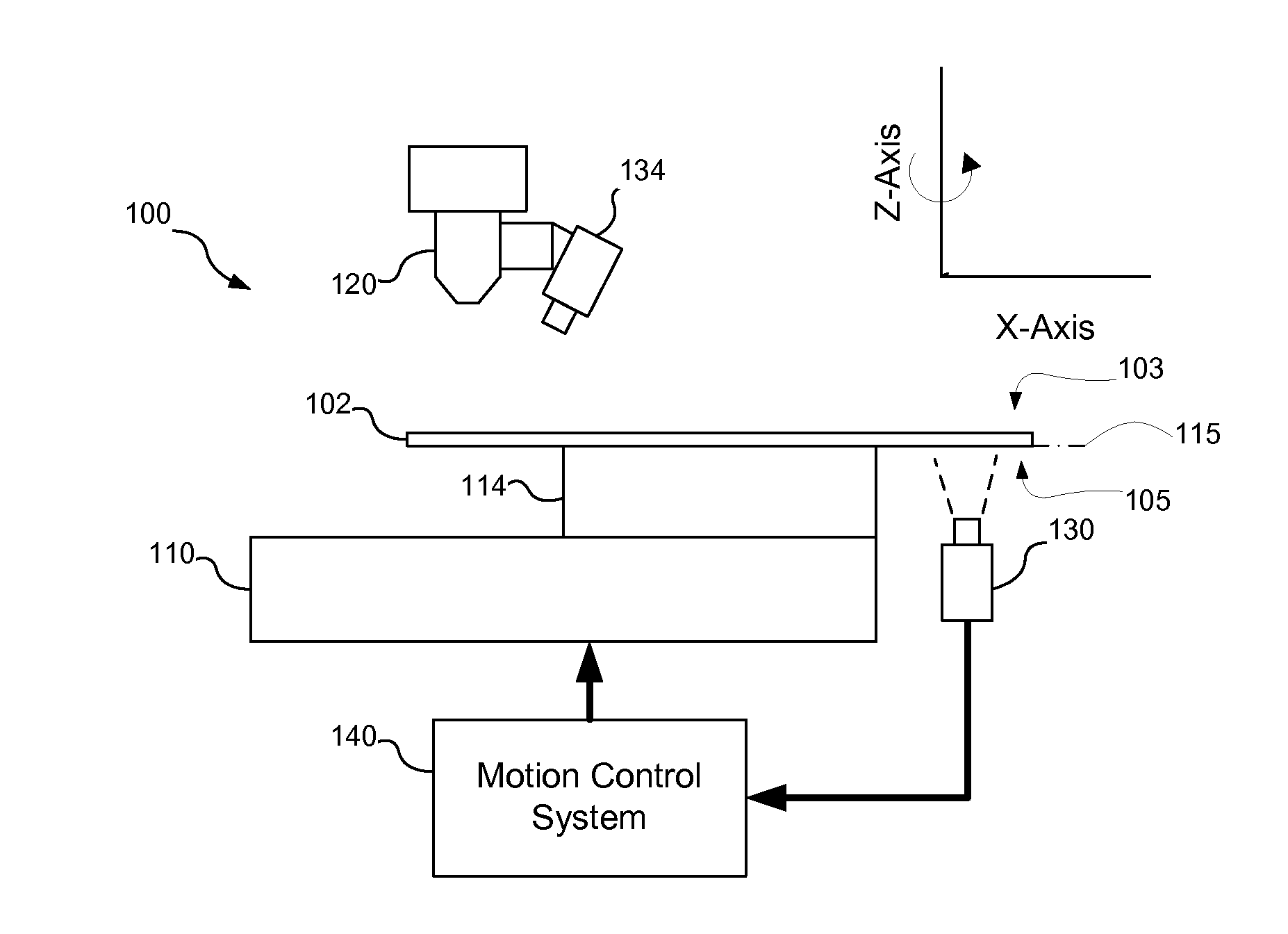
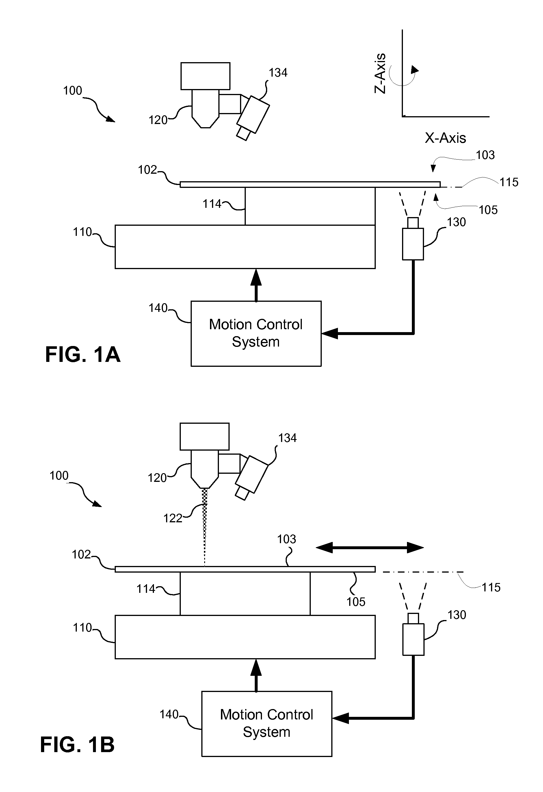
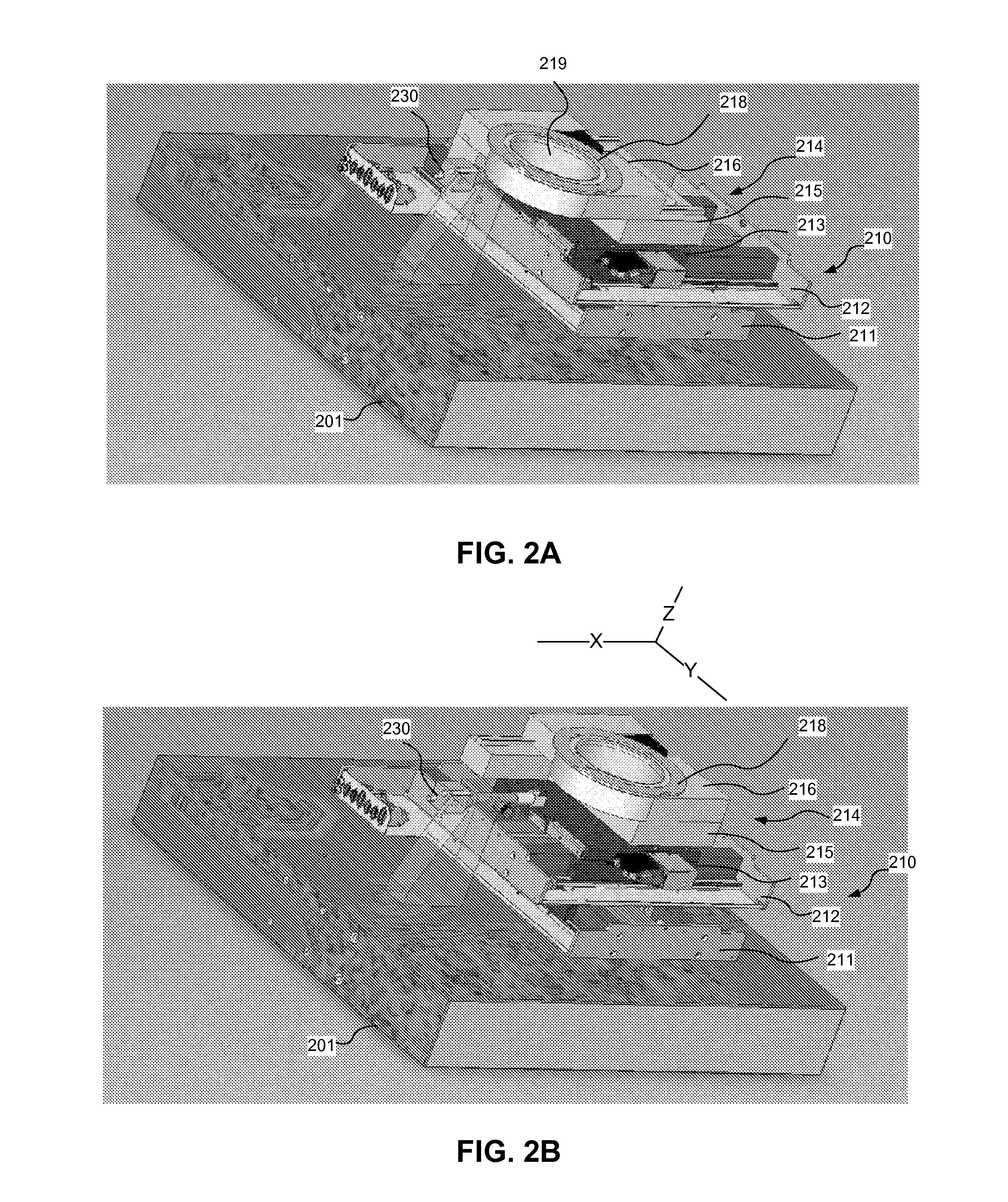
[0019]A laser machining system, consistent with embodiments of the present invention, may include an opposite side camera to provide workpiece alignment from an opposite side of the system (i.e., the side opposite the laser machining process). The opposite side camera may be used with an air bearing positioning stage that supports a workpiece. A portion of the stage and / or the opposite side camera may be moved to allow the opposite side camera to view and image a feature on the workpiece to be aligned with a laser beam on the opposite side. The laser beam to opposite side alignment may be used with back side scribing and / or dual side scribing of a workpiece with alignment from one or both sides of the workpiece. Laser machining systems and methods, consistent with embodiments of the present invention, may also be used to provide quasi-stealth scribing and multi-beam scribing.

[0020]As used herein, “machining” refers to any act of using laser energy to alter a workpiece and “scribing”...


PUM

PropertyMeasurementUnit
wavelengthaaaaaaaaaa
wavelengthsaaaaaaaaaa

Abstract

A laser machining system may include an opposite side camera to provide workpiece alignment from an opposite side of the system (i.e., the side opposite the laser machining process). The opposite side camera may be used with an air bearing positioning stage, and a portion of the stage and/or the opposite side camera may be moved to allow the opposite side camera to image a feature on the workpiece to be aligned. The opposite side alignment may be used with back side scribing and/or dual side scribing of a workpiece with alignment from one or both sides of the workpiece. Laser machining systems and methods may also be used to provide quasi-stealth scribing and multi-beam scribing.

Description

CROSS-REFERENCE TO RELATED APPLICATION[0001]The present application claims the benefit of U.S. Provisional Patent Application Ser. No. 61 / 267,190 filed Dec. 7, 2009, which is incorporated herein by reference.TECHNICAL FIELD[0002]The present invention relates to laser machining, and more particularly, laser machining systems with an opposite side camera and systems and methods for opposite side alignment, dual side machining, quasi-stealth scribing, and multi-beam stealth scribing.BACKGROUND INFORMATION[0003]Various laser machining applications involve alignment of a workpiece with a laser beam that is used to machine the workpiece. Existing laser machining systems include cameras that view an area of the workpiece to be machined to allow the workpiece to be positioned in proper alignment with the laser beam that performs the machining. In some applications, however, the laser beam should be aligned with a feature on an opposite side of a workpiece, i.e., on the side that faces away ...

Claims


Application Information

Patent Timeline
Patent Type & Authority Applications(United States)
IPC IPC(8): B23K26/00
CPCB23K26/041B23K26/0608B23K26/0676H01L33/0095B23K26/4075B23K2201/40B23K26/0738B23K26/042B23K26/40B23K2101/40B23K2103/50
Inventor SERCEL, JEFFREY P.MENDES, MARCOHILL, RANDAL R.BERGERON, NORMHSU, JEREMYLIU, LAWRENCE
Owner IPG PHOTONICS CORP
Why Eureka
Try Eureka