Cargo container handling cart and system using same

a technology for handling carts and cargo containers, applied in the field of cargo container handling carts, can solve the problems of poor maneuverability of trucks and railcars, inefficient use of conventional means of container transportation, and insufficient flexibility, and achieve the effect of overcompensating inefficiencies and disadvantages

Inactive Publication Date: 2011-06-09
PACECO
View PDF49 Cites 32 Cited by
  • Summary
  • Abstract
  • Description
  • Claims
  • Application Information

AI Technical Summary

Benefits of technology

[0007]A cargo container handling system using cargo container handling carts overcomes the inefficiencies and disadvantages inherent in prior art terminal cargo container transportation systems. A cargo container handling system according to the invention comprises a plurality of self-propelled handling carts each of which acts as a mobile platform capable of carrying one of the two ends of one or more containers on each end of the cart. Thus, rather than requiring a single, large conventional carrier such as railcar or truck chassis to support and carry one container, substantially shorter carts according to the invention can be used to support one or more containers by supporting only the ends of the containers rather than the entire length of each container. At least two carts 10 are used to support a single container; one to support the rear end of a container C, and another cart to support the front end, as shown in FIG. 2.

Problems solved by technology

On the other hand, trucks and railcars have poor maneuverability and inadequate flexibility.
Since container sizes generally vary, inefficient use of these conventional means of container transport results.

Method used


Image

  • Cargo container handling cart and system using same
  • Cargo container handling cart and system using same
  • Cargo container handling cart and system using same

Examples


embodiment 70

[0054]A pivoting embodiment 70 of a cargo container handling cart is shown in FIGS. 9A-9C. The pivoting embodiment, like the embodiment discussed above, has two end portions 72 supported on wheels 73, each end portion having an inner edge 74. A pivot arm 76 extends inwardly from each inner edge 74. The pivot arms overlap and are pivotally joined about a pivot pin 78 which provides a vertical pivot axis about which the end portions 72 mutually pivot. The ability of the end portions 72 to pivot permits the cart or a container train formed using multiple handling carts to run on curved tracks. A pivot cart may be equipped with a steering control system and a pivot angle control system.

[0055]Each end portion 72 includes a support surface 80 having cart pins 82 for mating engagement with the corner casting holes of corner fittings as discussed above. Corner guides 84 are provided at each inner corner 86 of each end portion 72. With additional reference to FIGS. 10A and 10B, each corner g...

embodiment 100

[0057]Alternate embodiments of a pivoting cart such as that shown in FIGS. 9A-9C are seen in FIGS. 9D and 9E. The pivoting cart 96 shown in FIG. 9D includes transverse container guides 98 on each of the support surfaces 80 for guiding a container end onto the support surface 80. The embodiment 100 shown in FIG. 9E includes inner edge container guides 102 extending upwardly from the inner edge 104 of each of the support surfaces 80. And each of the embodiments 96, 100 also includes upwardly extending lateral container guides 106, 108, for guiding a descending container end onto one of the support surfaces 80.

[0058]A close-up view of the container guides for the pivoting embodiment of the handling cart shown in FIG. 9E is illustrated in FIG. 12. Inner end and lateral container guides 102 and 108, respectively, are provided at the inner corners 110 of each frame member 112 of a pivoting container handling cart. Each container guide 102, 108 has a sloped surface 114 for guiding containe...

embodiment 10

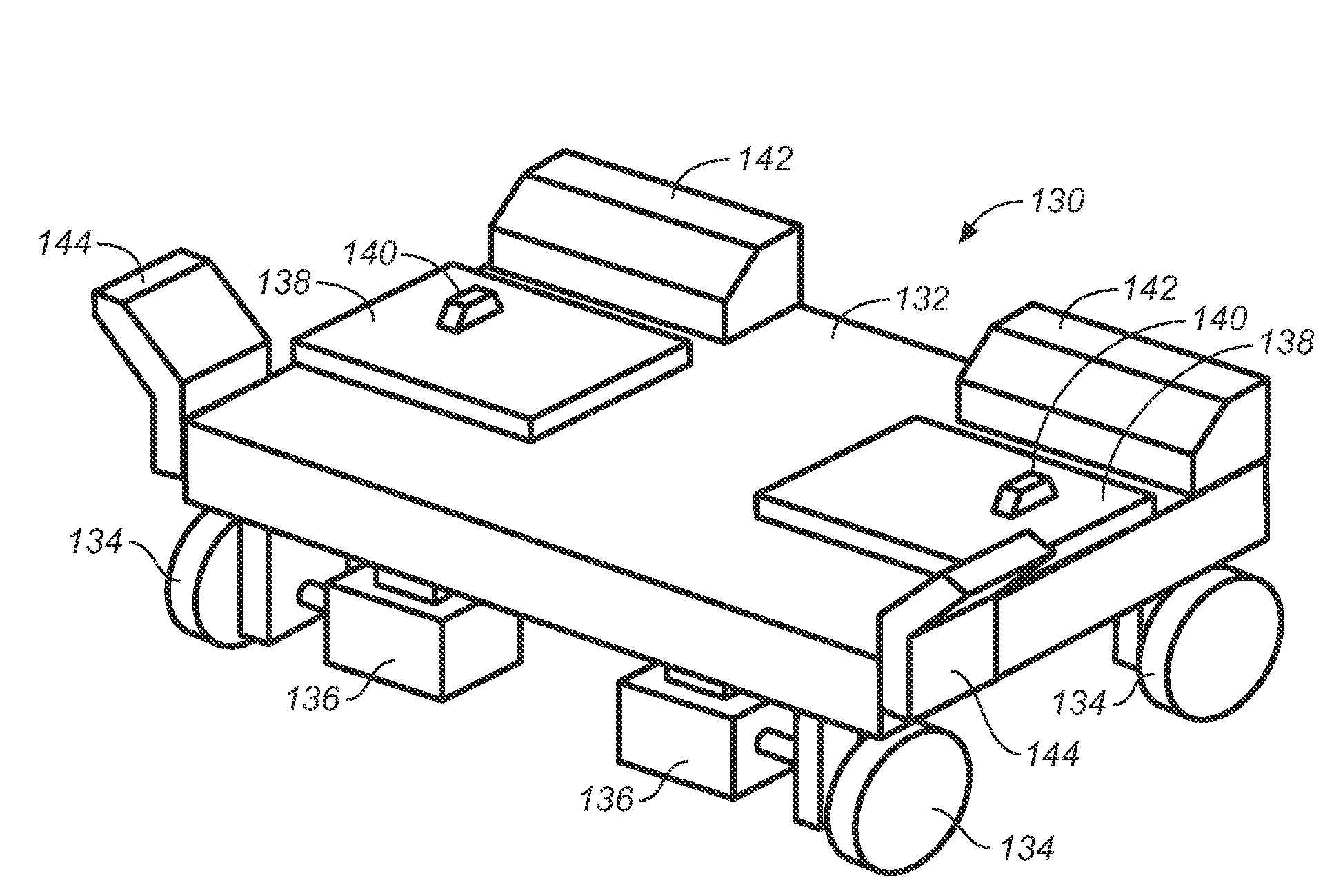
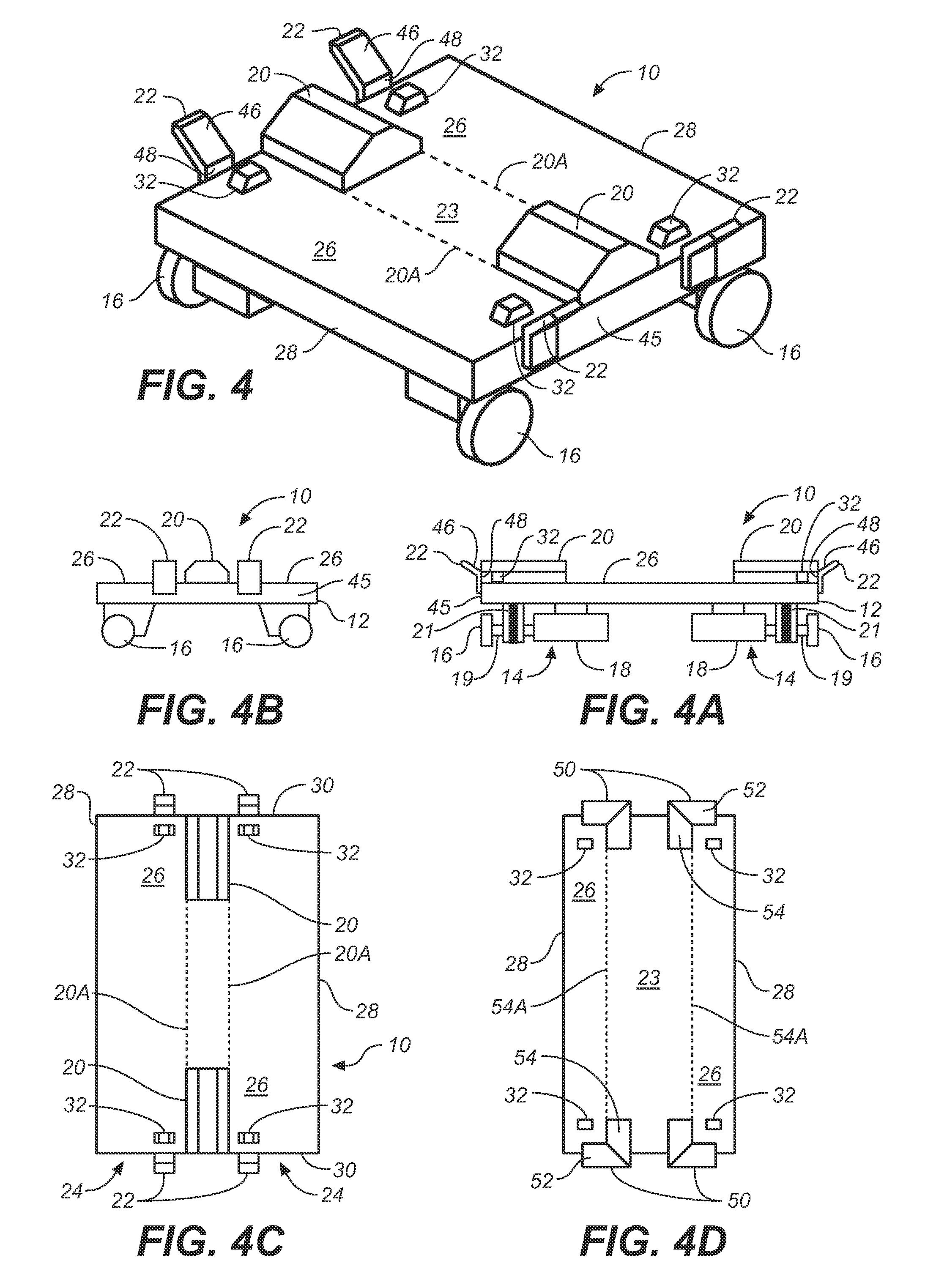
[0063]The embodiment of a handling cart, indicated at 250 in FIG. 17, is similar to embodiment 10, shown in FIG. 4, but will support four container ends rather than just two container ends. Each cart 250 in this embodiment comprises a structural frame 252 and a cart drive system 254 including wheels 256, motor and braking systems 258, a suspension system 260, and one or more power sources (not shown). The top surface 262 is functionally separated into two end portions 264 between which are mounted transverse container guides 266, 268. In the illustrated embodiment, container guides consist of outer container guides 266 and inner container guide 268, but it is intended that the configuration or arrangement of the container guides disposed between the two end portions 264 not be so limited. Each end portion 264 is functionally separated into first and second support surfaces 270, 272, each support surface having a width suitable for supporting a standard cargo container C. Support sur...


PUM


Abstract

A cargo container handling cart and system comprises a plurality of cargo container handling carts 10, each cart comprising a frame 12 supported on wheels 16, the frame having two support surfaces 26 and at least one centrally disposed container guide 20, each support surface having two cart pins 32, and a cart end edge 28, the support surface 26 bounded by the container guide 20 and the cart end edge 28 for supporting the end of a cargo container, wherein the support surface 26 has a width substantially equivalent to a standard cargo container, the container guide 20 abuts a container end resting on one of the support surfaces 26, and the cart pins 32 extend upwardly from the support surface 26 between the container guide 20 and the cart end edge 28 for engaging with the corner casting holes of the corner fittings of the container end for holding the container end on the support surface 26 against the container guide 20.

Description

CROSS-REFERENCE TO RELATED APPLICATIONS[0001]This application claims the benefit of U.S. Patent Application Ser. No. 61 / 267,347, filed Dec. 7, 2009, and U.S. Patent Application Ser. No. 61 / 299,969, filed Jan. 30, 2010, both of which are hereby incorporated by reference.BACKGROUND[0002]1. Field of the Invention[0003]This invention is related to systems for transporting cargo containers within container terminals and, more particularly, to a cargo container handling cart capable of supporting the ends of two or more adjacent cargo containers, a plurality of which carts may be used to form and transport a “train” of cargo containers within a container terminal or between separate terminals.[0004]2. Prior Art[0005]Operations within container terminals require dedicated equipment and methods for transporting containers between various cargo handling cranes and other cargo handling equipment. For example, terminal operators commonly use trucks with chassis to transport containers from doc...

Claims


Application Information

Patent Timeline
Patent Type & Authority Applications(United States)
IPC IPC(8): B62B3/04
CPCB62B5/0063B62B2207/00B62B5/0093B62B5/0086
Inventor TAKEHARA, TORUTAM, PHILIPTAKAHARA, TATSUSHI
Owner PACECO
Why Eureka
Try Eureka