
Ecologically Friendly Generator

a generator and environmental protection technology, applied in the field of generators, can solve the problems of inability to connect to the grid, too large battery consumption, and high cost of portable power generation equipment to purchase and maintain, and achieve the effects of simple design, convenient use, and convenient us

Inactive Publication Date: 2011-06-09
MULLINS RAYMOND
View PDF4 Cites 1 Cited by
  • Summary
  • Abstract
  • Description
  • Claims
  • Application Information

AI Technical Summary

Benefits of technology

[0006]Embodiments of the invention provide portable electrical power using a generator that is inexpensive to buy and operate, compact, efficient, uses many types of fuel and can be used indoors safely. This invention is simple in design, has very few moving parts, runs on almost any vaporized or gaseous combustible fuel, and can be used indoors when using certain types of fuel.
[0007]An object of the invention is to provide portable power generation reliably, cheaply and efficiently with the ability to use ecologically friendly fuels.

Problems solved by technology

Portable generators and alternators powered by a combustion engine are used where electrical power is needed but connection to the grid is not practical and the demand is too great for battery use.
Portable power generation equipment is expensive to purchase and to maintain.
Proper operation of the equipment depends on a multitude of moving parts, is bulky and heavy.
Portable power generating equipment is limited to outdoor use due to the pollutants generated by the combustion engine used to power the generator.
Today's portable power generating equipment is inefficient due to the amount of fuel required to move the parts of the engine that provides power to the generator.

Method used


Image

  • Ecologically Friendly Generator
  • Ecologically Friendly Generator
  • Ecologically Friendly Generator

Examples


Embodiment Construction

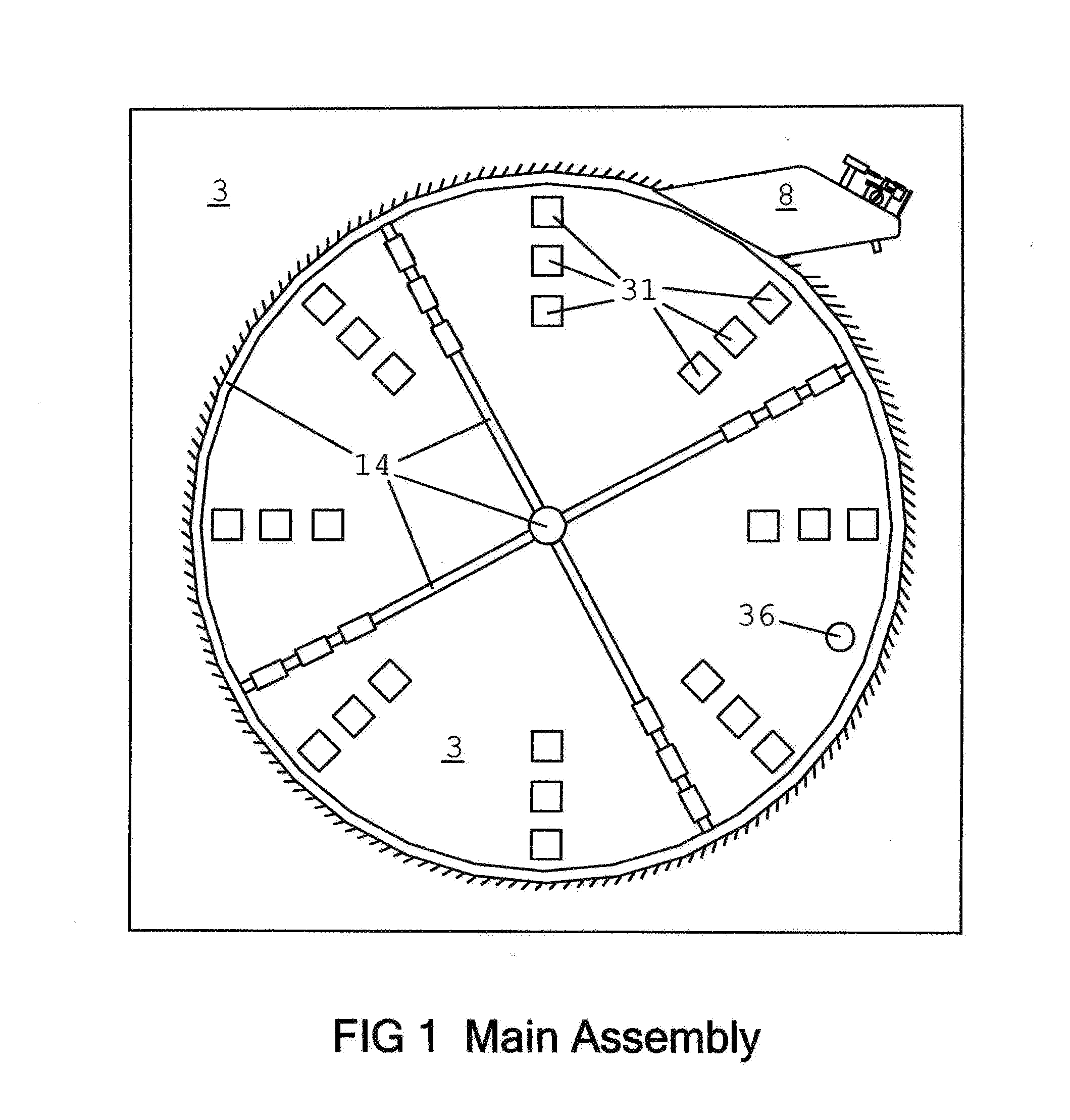
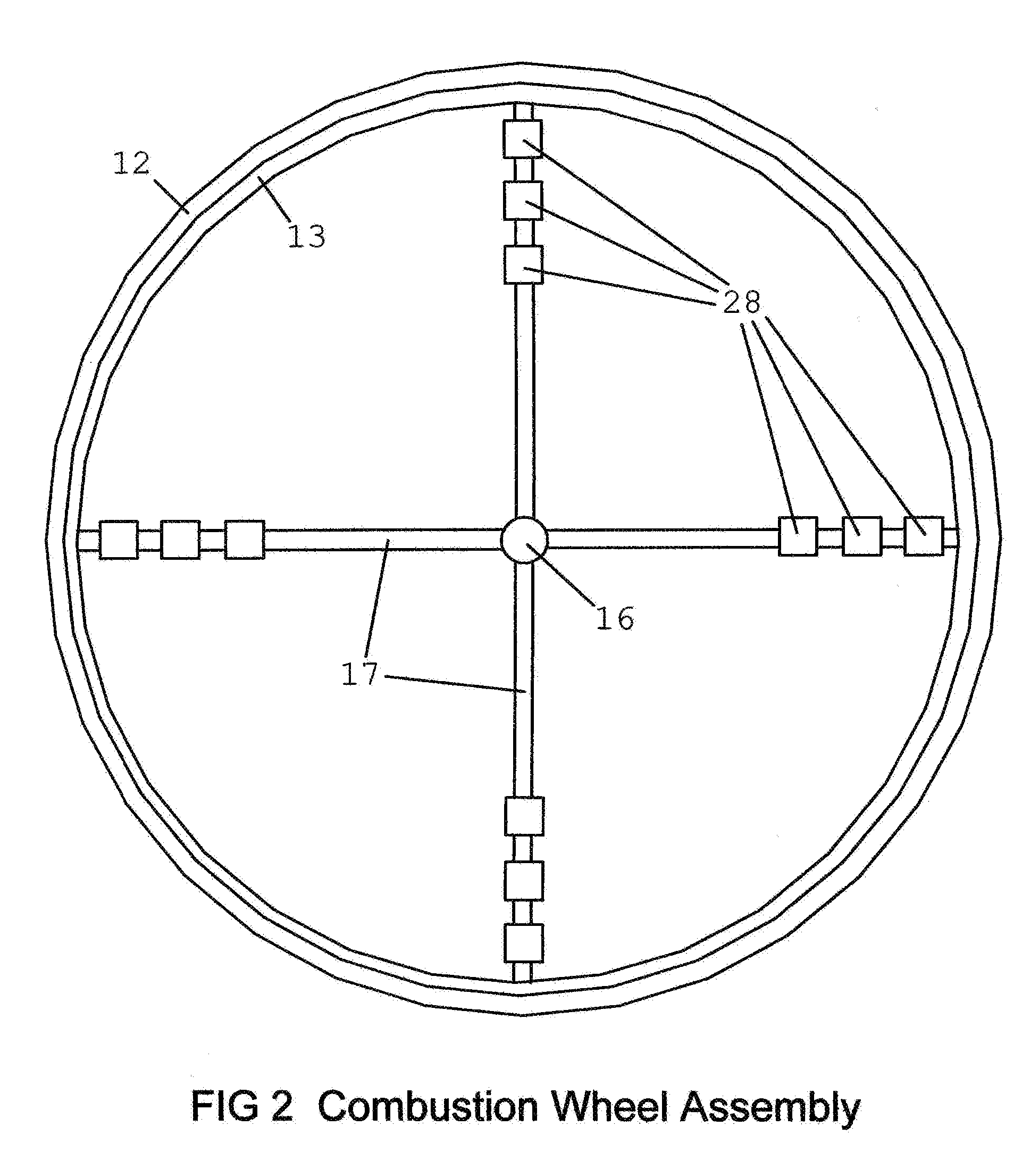
[0022]In the description of embodiments that follows, the following definitions are used to describe various components described below and in the figures:

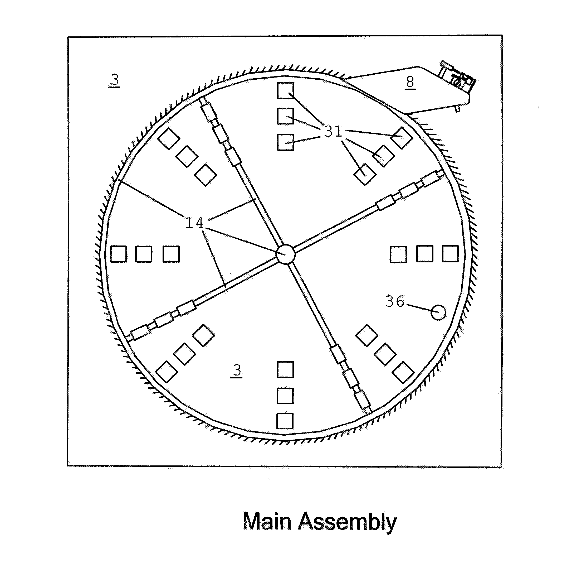
TABLE 1Identification Tags Used in the Drawings1BatteryAny voltage or size of rechargeable battery.Can be used to store the energy generated by the Pickup Coils 31.2Bridge RectifierConverts the alternating voltage / current to direct voltage / current.3CaseThe housing used to support the Pickup Coils 31, Trigger Sensor 36, Combustion WheelAssembly 14 and Combustion Head Assembly 8.4Charging SectionCan comprise: Pickup Coils 31, Bridge Rectifier 2, Voltage Regulator 37, and Battery 1.5CoilDevelops a high voltage potential to produce a spark from the Igniter 27.High Voltage Spark Source (HVSS).6Combustion ChamberArea between Combustion Head Side Panels 10, Combustion Head Baffle 9 andCombustion Wheel 13. This is the area where combustion occurs.7Combustion HeadProvides a chamber for combustion to occur.8Combustion Head AssemblyThe Combu...


PUM


Abstract

The present invention relates to the field of generators and engines. Specific embodiments of the invention include a generator comprising: a combustion chamber for combusting fuel to produce a high pressure flow of air or gas; a combustion wheel comprising: a rim with circumferentially spaced combustion plates protruding radially outward from the rim for receiving the high pressure flow of air or gas; a wheel hub providing means for rotating the wheel on an axis of rotation upon interaction of the high pressure flow on the combustion plates; spokes comprising one or more magnets, wherein the spokes operably connect the hub to the rim and provide for the magnets to interact with pick-up coils; pick-up coils for receiving energy from the magnets during rotation of the wheel and for producing electrical energy therefrom; and optionally comprising a battery for receiving and storing energy from the pick-up coils.

Description

CROSS-REFERENCE TO RELATED APPLICATIONS[0001]This application relies on the disclosure of and claims the benefit of the filing date of U.S. Provisional Application No. 61 / 250,676, filed Oct. 30, 2009 the disclosure of which is incorporated by reference herein in its entirety.BACKGROUND OF THE INVENTION[0002]1. Field of the Invention[0003]The present invention relates to the field of generators.[0004]2. Description of the Related Art[0005]The demand for electricity in all of its forms continues to grow. With today's technology, to use electricity you have to be hooked to the grid (plugged in to an outlet), use a battery or use a portable generator powered by a combustion engine. Generators, and later alternators, have been used in automobiles to provide power generation to charge the battery. Portable generators and alternators powered by a combustion engine are used where electrical power is needed but connection to the grid is not practical and the demand is too great for battery u...

Claims


Application Information

Patent Timeline
Patent Type & Authority Applications(United States)
IPC IPC(8): H02K7/18F01L7/00
CPCH02K7/1807F02B43/10
Inventor MULLINS, RAYMOND
Owner MULLINS RAYMOND
Learn More