

Pillar structure of vehicle and method for manufacturing the same
a technology for pillars and vehicles, applied in vehicle arrangements, roofs, transportation and packaging, etc., can solve problems such as difficult control of pillar deformation, and achieve the effect of increasing the flow of cooling water and being easy to manufactur
- Summary
- Abstract
- Description
- Claims
- Application Information
AI Technical Summary
Benefits of technology
Problems solved by technology
Method used
Image

Examples
first embodiment
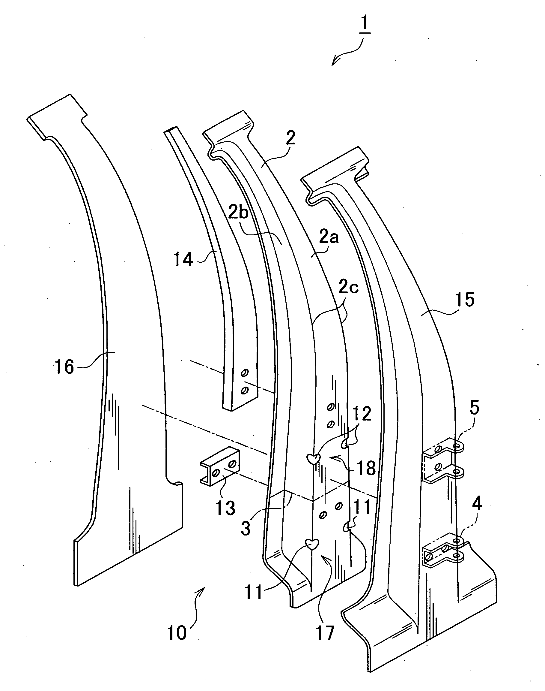
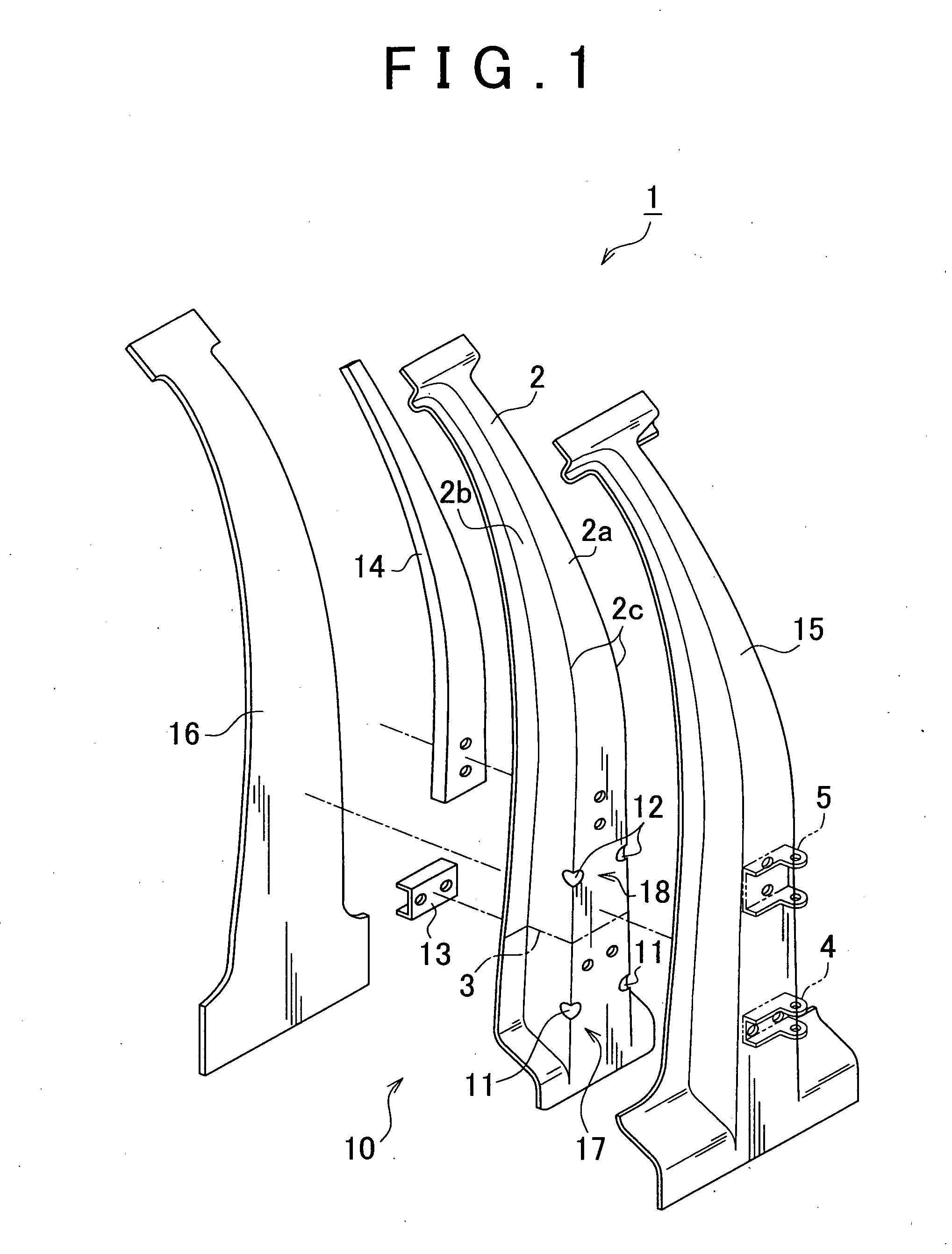
[0063]FIG. 1 is an exploded perspective view of a center pillar structure, which is the pillar structure of a vehicle according to the invention. FIG. 2 is a side view of the center pillar structure shown in FIG. 1. As shown in FIG. 1 and FIG. 2, the center pillar structure 1 of a vehicle, such as an automobile, includes a center pillar 10. The center pillar 10 includes an outer panel 15, an inner panel 16, an outer reinforcement 2 and hinge reinforcements 13 and 14. The outer panel 15 and the inner panel 16 extend from a rocker to a roof side rail. The outer reinforcement 2 and the hinge reinforcements 13 and 14 are arranged in an internal space defined by the outer panel 15 and the inner panel 16.
[0064]The outer panel 15 may be regarded as an outer shell member according to the aspect of the invention. The inner panel 16 may be regarded as an outer shell member according to the aspect of the invention. The outer reinforcement 2 may be regarded as a reinforcement member according t...
second embodiment
[0103]FIG. 16 is a perspective view of a center pillar structure, which is the pillar structure of a vehicle according to the invention. FIG. 17 is a front view of the center pillar structure shown in FIG. 16. As shown in FIG. 16 and FIG. 17, the center pillar structure 1 includes an outer reinforcement 2. The outer reinforcement 2 is formed so that high-tensile steel plates are jointed via a laser welding seam 3. The upper end portion of the outer reinforcement 2 is connected to a roof side rail, and the lower end portion of the outer reinforcement 2 is connected to a rocker.
[0104]An outward projected non-quenched portion 6 is formed in the outer reinforcement 2 between a portion to which a lower hinge 4 of a door is attached and a portion to which an upper hinge 5 of the door is attached. In addition, an outward projected non-quenched portion 7 is formed in the outer reinforcement 2 between the portion to which the lower hinge 4 is attached and a portion connected to the rocker. I...
third embodiment
[0119]For example, as shown in FIG. 26 and FIG. 27, when the outer reinforcement 2 has cutout beads 11 and 12 instead of the non-quenched portions 6 and 7 in the third embodiment as well, it is possible to reduce the bending moment generated in the outer reinforcement 2 by lifting of the other vehicle in the event of a side collision.
[0120]In the outer reinforcement 2 shown in FIG. 26, a pair of outer edge line portions respectively have the beads 11 and 12. In the outer reinforcement 2, the number of beads 12 formed in the upper portion with respect to the portion to which the lower hinge 4 is attached is larger than the number of beads 11 formed in the lower portion with respect to the portion to which the lower hinge 4 is attached, while, on the other hand, the thickness and material are varied between the lower portion and the upper portion. Thus, the strength of the member of the upper portion with respect to the laser welding seam 3 is higher than the strength of the member of...
PUM
| Property | Measurement | Unit |
|---|---|---|
| height | aaaaa | aaaaa |
| structure | aaaaa | aaaaa |
| strength | aaaaa | aaaaa |
Abstract
Description
Claims
Application Information