
Apparatus for simultaneously performing gamma correction and contrast enhancement in display device

Inactive Publication Date: 2011-06-09
RENESAS ELECTRONICS CORP
View PDF13 Cites 12 Cited by
  • Summary
  • Abstract
  • Description
  • Claims
  • Application Information

AI Technical Summary

Benefits of technology

[0008]The inventor has discovered that the image processing apparatuses disclosed in the '724 and '353 applications, however, undesirably requires large hardware, since the edge enhancement and the gamma correction are performed in separate units. According to the inventor's study, use of a calculation circuit which simultaneously performs gamma correction and contrast enhancement effectively reduces the hardware required for the same.
[0013]The present invention allows performing gamma correction and contrast enhancement with reduced hardware.

Problems solved by technology

The inventor has discovered that the image processing apparatuses disclosed in the '724 and '353 applications, however, undesirably requires large hardware, since the edge enhancement and the gamma correction are performed in separate units.

Method used


Image

  • Apparatus for simultaneously performing gamma correction and contrast enhancement in display device
  • Apparatus for simultaneously performing gamma correction and contrast enhancement in display device
  • Apparatus for simultaneously performing gamma correction and contrast enhancement in display device

Examples


first embodiment

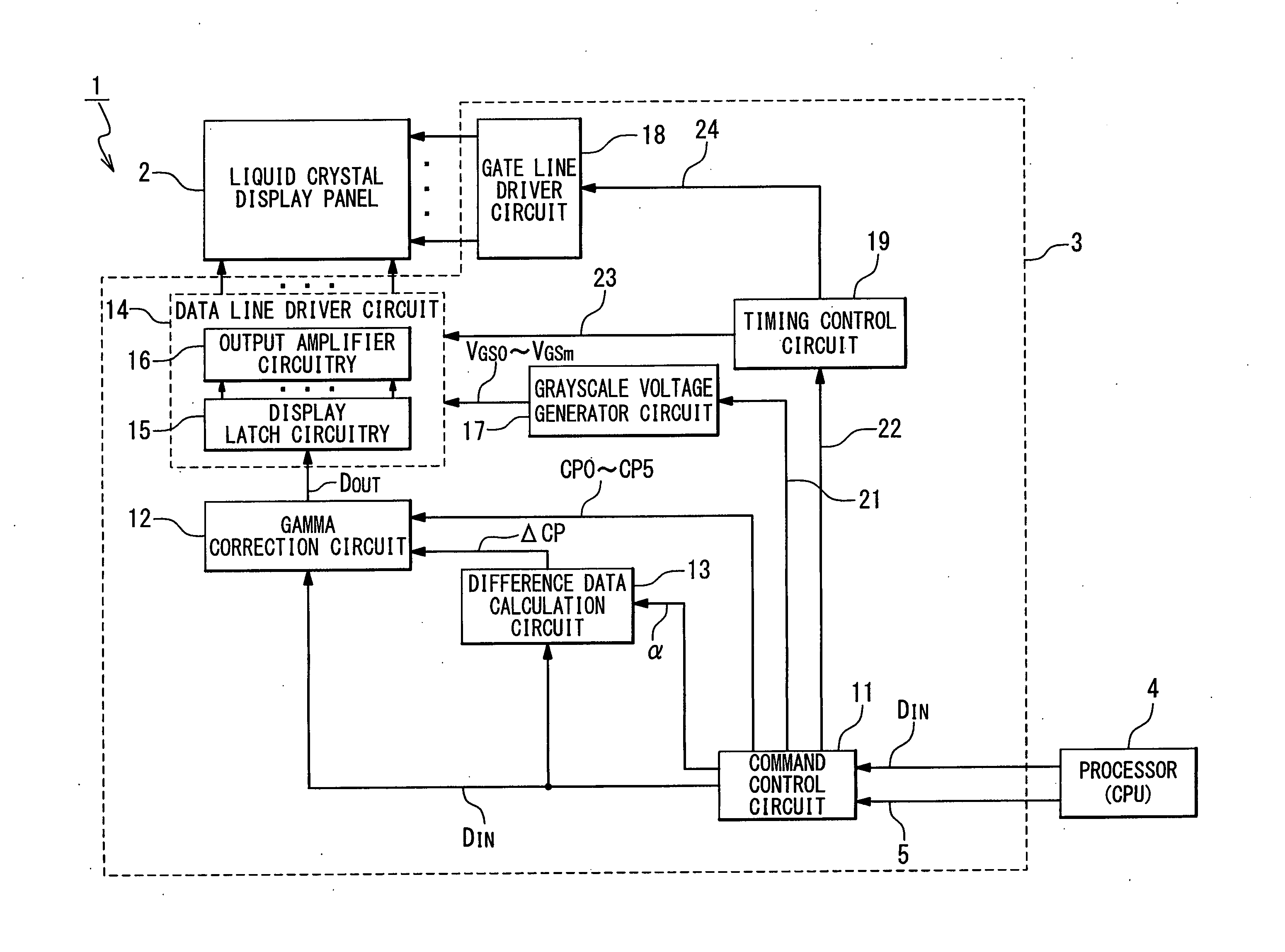
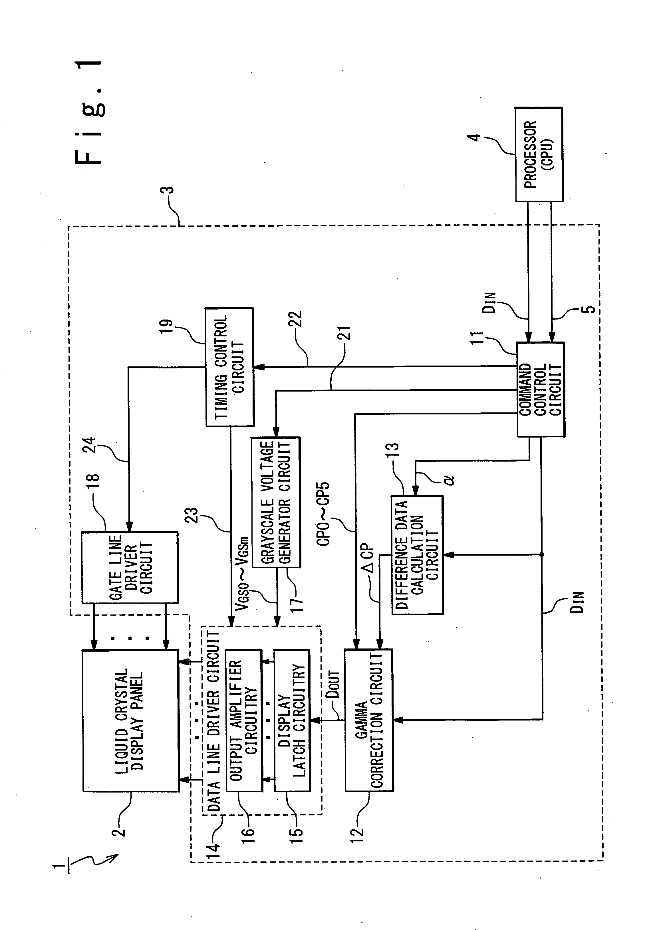
[0025]FIG. 1 is a block diagram showing an exemplary configuration of a liquid crystal display device 1 in a first embodiment of the present invention. The liquid crystal display device 1 is provided with a liquid crystal display panel 2 and a controller driver 3, and configured to display an image on the liquid crystal panel 2 in response to input image data DIN and control signals 5 received from a processing unit 4. It should be noted here that the input image data DIN are image data of an image to be displayed on the liquid crystal display panel 2; the input image data DIN specify the grayscale levels of respective sub-pixels of respective pixels of the liquid crystal display panel 2. In this embodiment, each pixel is provided with a sub-pixel showing red (R sub-pixel), a sub-pixel showing green (G sub-pixel) and a sub-pixel showing blue (B sub-pixel). In the following, input image data DIN for specifying an R sub-pixel may be referred to as input image data DINR. Correspondingl...

second embodiment

[0074]FIG. 7 is a block diagram showing an exemplary configuration of the liquid crystal display device 1 in a second embodiment of the present invention. In the second embodiment, enlargement processing is performed for enlarging the image of the input image data DIN by a factor of two in both of the vertical and horizontal directions. More specifically, image data for 2×2 pixels (enlarged data DENL) are generated from input image data DIN for one pixel, and the gamma correction is performed on the enlarged data DENL by the gamma correction circuit 12.

[0075]In detail, the controller driver 3 additionally includes an image memory 25 and an enlargement processing circuit 26. The image memory 25 temporarily stores the input image data DIN and forwards the stored input image data DIN to the enlargement processing circuit 26. The image memory 25 is configured to store the input image data DIN for at least one line of pixels (pixels connected to one gate line). The enlargement processing...


PUM


Abstract

A display device is provided with a display panel; a correction circuit which performs gamma correction on target image data in response to correction data specifying a gamma curve; and a driver circuit driving the display panel in response to gamma-corrected data received from the correction circuit. The correction circuit is configured to perform approximate gamma correction in accordance with a correction expression in which the target image data is defined as a variable of the correction expression and coefficients of the same are determined on the correction data, and to modify the correction data in response to target image data associated with the target pixel of the gamma correction and the pixel adjacent to the target pixel.

Description

INCORPORATION BY REFERENCE[0001]This patent application claims a priority on convention based on Japanese Patent Application No. 2009-278884 filed on Dec. 8, 2009. The disclosure thereof is incorporated herein by reference.BACKGROUND OF THE INVENTION[0002]1. Field of the Invention[0003]The present invention is related to a display device, a display panel driver and an image data processing unit, more particularly, to a technique for performing image data processing for image contrast enhancement.[0004]2. Description of the Related Art[0005]Output devices, such as display devices and printers, are often configured to perform image processing on image data for improving the image quality. Such image processing may include contrast enhancement and / or edge enhancement. The contrast enhancement is image processing for making the image sharp by brightening bright portions of the image and darken dark portions of the same, and the contrast enhancement is image processing for making the ima...

Claims


Application Information

Patent Timeline
IPC IPC(8): G09G5/10
CPCG09G3/3648G09G2320/0673G09G2320/066G09G2320/0276
Inventor FURIHATA, HIROBUMI
Owner RENESAS ELECTRONICS CORP
Learn More