Multi-dump metering valve

a multi-dump metering and valve technology, applied in the field of mechanical valves, can solve the problems of increasing the weight and power consumption of equipment, increasing the weight of equipment, and unfavorable high electrical power demands in helicopters

Active Publication Date: 2016-02-23
DONMARK HLDG
View PDF5 Cites 2 Cited by
  • Summary
  • Abstract
  • Description
  • Claims
  • Application Information

AI Technical Summary

Benefits of technology

[0007]In one aspect, the invention provides an improved multi dump metering valve over the valve in Brooke, having an even further reduced surface area on those surfaces which are disposed normally to a direction of movement so as to be even less affected by hydrostatic and hydrodynamic forces directed so as to oppose its movement. This may be achieved in part by improved annular seal members that present a reduced surface area disposed normally to a direction of movement, and in part by obviating the need for the spacer arms and the guide post of the Brooke apparatus. As a result of the reduced surface area, the load required to actuate the valve to the open position is significantly reduced from that of the Brooke apparatus. In addition, the outer assembly of the valve in the present invention is biased toward the open position of the valve, which further reduces the load required to open the valve. For example, the load on the actuator cable in the Brooke apparatus is approximately 250 lbs., whereas the load to open the valve of the present invention, for a comparably sized valve, is approximately 50 lbs. As a result, a much smaller actuator motor and associated actuator hardware are needed to open and close the valve of the present invention, with the significant advantage that the actuator motor and actuator hardware may be housed on the valve assembly itself rather than being housed in a separate and bulky control head. This advantage greatly simplifies the control hardware and obviates the need for a bulky control head, which may be replaced with a simple and significantly lighter cargo hook mechanism for use with the present invention. A weight reduction of approximately 50% may be achieved by the reduced hardware required, and this is significant for ground personnel who are tasked with manipulating the bucket and control mechanism during fire fighting operations.
[0008]The advantage of being able to use a significantly smaller motor in the present invention translates to a significantly lower power demand on the electrical system of the aircraft. For example, the electrical load required for the present invention has been reduced to approximately 5 amps, from the approximately 25 amps required by the Brooke apparatus. This reduced electrical load means that the controller may be much smaller and may be housed directly on the bucket rather than in the helicopter, which means that the equipment need not go through the aircraft certification process that would otherwise be required in order for it to be onboard the aircraft. This results in a significant cost reduction to the manufacture as well as the aircraft operator.
[0009]In another aspect, the present invention provides a more serviceable valve than that of the Brooke apparatus. A significant wear point has been found to be the seals, and the configuration of the present invention in conjunction with the annular seal members of the present invention make it easier and faster to service than the Brooke apparatus.
[0014]In some embodiments, a position sensor is mounted on the drum wherein the position sensor provides feedback to an operator as to the position of the drum which can be correlated to a position of the outer assembly in relation to the inner assembly thereby assisting the operator to partially open the valve.

Problems solved by technology

There are problems associated with each of these valves.
With the flapper vales, there are significant forces imparted to the valve by a full head of water that tend to resist the hinging of the flapper member and thereby resists the opening of the flapper valve, which requires a powerful motor to actuate the flapper, resulting in increased weight and power consumption.
High electrical power demands in a helicopter is undesirable since the onboard equipment need to undergo rigorous testing and certification, and the associated cabling needed for such high demands increases the weight of the equipment substantially.
Furthermore, the operation of the flapper valve may create turbulent flow, causing the water to disperse laterally as it is dumped.
In fire-fighting, lateral dispersal may be undesirable as the water may be more susceptible to evaporation before reaching the ground and also because some of the water may overshoot the desired target.
With the butterfly valves, they tend to cause lateral dispersal when operated as a metering valve and may be difficult to seal as one plate may be located inside the bucket and the other plate may be located outside the bucket.

Method used


Image

  • Multi-dump metering valve
  • Multi-dump metering valve
  • Multi-dump metering valve

Examples


Embodiment Construction

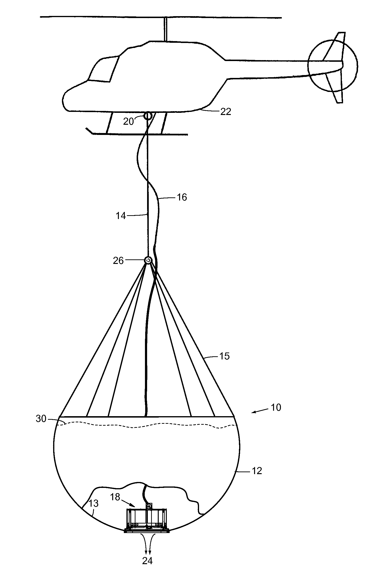
[0025]Referring to FIG. 1, a fire-fighting bucket is shown generally as 10. The bucket 10 may include a reservoir 12 for containing a volume of fluid 30. The reservoir 12 may include a bottom interior surface 13 having a valve 18 in accordance with an embodiment of the present invention thereon for controllably releasing a stream 24 of fluid over a fire, for example. The reservoir 12 may be suspended from a suspension mechanism 26 by support cables 15 and the suspension mechanism 26 may be suspended from cargo hook 20 of helicopter 22 by support cable 14. A control cable 16 may be connected between the helicopter 22 and the valve 18 to transmit instructions from a controller to the valve. The control cable 16 may be an electrical cable, for example.

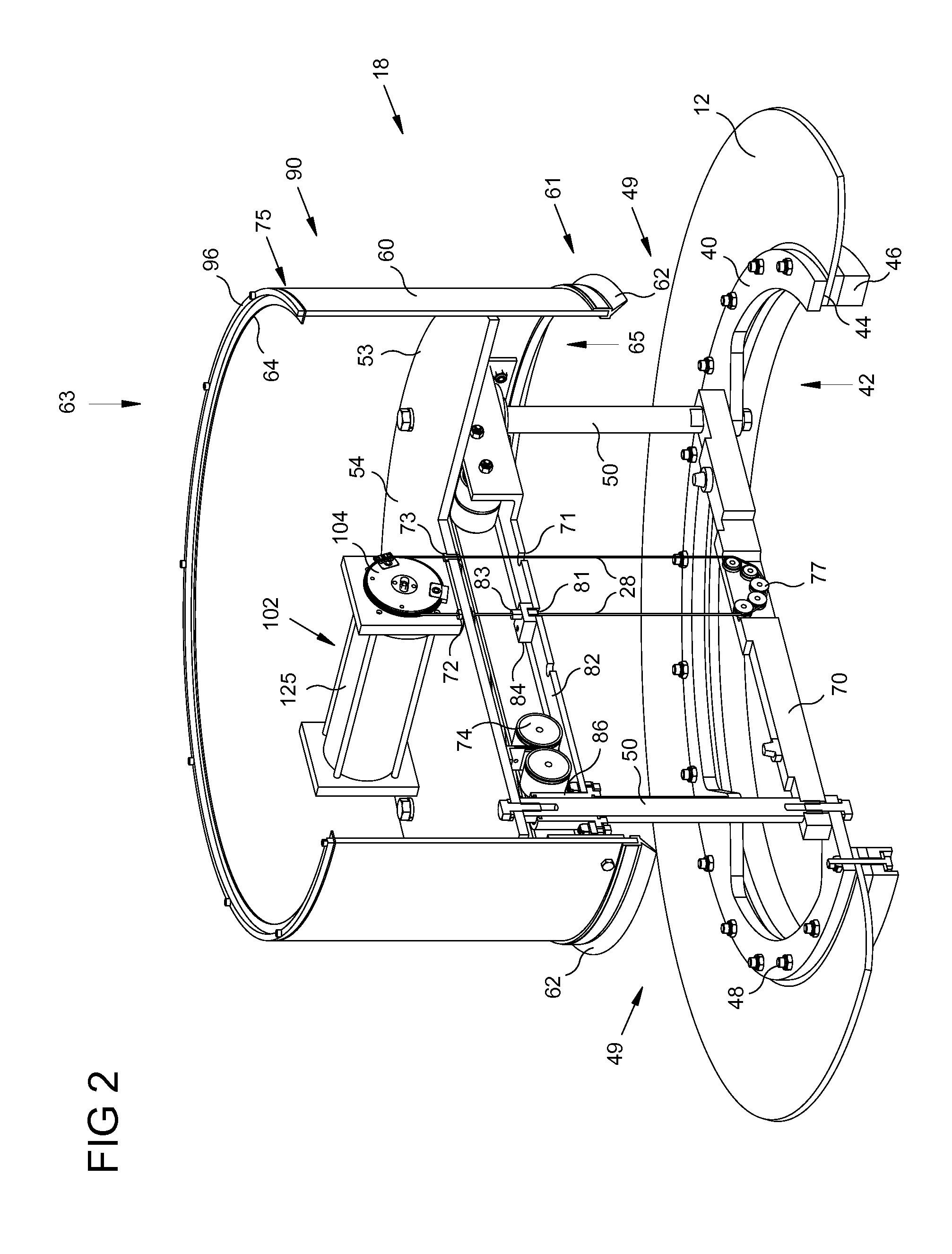
[0026]Referring to FIGS. 2-7, valve 18 may have a flat circular base plate 40 having a central circular outlet 42 extending therethrough. A bottom portion 44 of the base plate 40 defines a seat to receive an edge portion of the reservoir ...


PUM


Abstract

Valves having an inner assembly comprising: a base plate spaced apart from a top plate to define therebetween an open side, the base plate defining an outlet; an outer assembly comprising solid side walls and being movable relative to the inner assembly between open and closed positions, an upper portion of the solid side walls seal with the top plate only when the outer assembly is in the closed position, a lower portion of the solid side walls seal with the base plate only when the outer assembly is in the closed position, wherein the open position allows flow through the valve via the open side portion and the outlet of the outer assembly; and an actuator mounted to the inner assembly and connected to the outer assembly to move the outer assembly between the open and closed positions in response to electrical control signals.

Description

FIELD OF THE INVENTION[0001]The invention pertains to mechanical valves, in particular to mechanical valves that may be used to regulate fluid flow from reservoirs such as aerial firefighting buckets.BACKGROUND[0002]Helicopter carried dump-buckets are well known for use in fighting forest fires. These buckets, at their simplest, may comprise a rigid or flexible reservoir or body for holding a volume of water, a sling to suspend the reservoir from a helicopter, a valve, and an actuator which is controlled from inside the helicopter to operate the valve to release the water from the reservoir over the fire.[0003]In some prior art buckets, the valve may consist of a simple flapper valve located on a bottom interior surface of the reservoir and operated by a remotely controlled actuator, for example. A flapper valve typically includes a base plate having an outlet therein, a flat flapper member disposed over-top of the base plate so as to block the outlet, and a hinge connected between ...

Claims


Application Information

Patent Timeline
Patent Type & Authority Patents(United States)
IPC IPC(8): A62C3/02A62C3/08A62C31/28A62C8/02
CPCA62C3/0235A62C3/0228A62C3/08A62C31/28A62C8/02B64D1/16
Inventor TOECKES, MARKTRAUTMAN, EARL D.
Owner DONMARK HLDG
Why Eureka
Try Eureka