Ink jet printing apparatus and method

a printing apparatus and jet printing technology, applied in the field of jet printing apparatuses and methods, can solve the problems of black and white stripe-like density unevenness in printed images, decline in precision in conveying print media, and error in conveying distance, so as to suppress image defects

Inactive Publication Date: 2011-06-09
CANON KK
View PDF10 Cites 14 Cited by
  • Summary
  • Abstract
  • Description
  • Claims
  • Application Information

AI Technical Summary

Benefits of technology

[0015]An object of the present invention, from the above viewpoint, is to present an ink jet printing apparatus and method that enables the suppression of image defects due to conveyance distance errors by way of employing suitable mask patterns in accordance with dot size and density.

Problems solved by technology

It is known that in ink jet printing apparatuses black and white stripe-like density unevenness occurs in printed images, caused by errors in the conveyed distance.
The dimensional variation of each of the parts of this kind of conveyance mechanism causes a decline in precision in conveying the print medium, and causes the occurrence of the above mentioned error in the conveyed distance.
In addition to the above mentioned decline in precision in conveying the print medium, it is also thought that flicking of the printing paper, that is, the existence of a kicking phenomenon when the tail end of the printing paper breaks free from the nip of the paper feed and pinch rollers, is also a cause of conveyance distance errors.
Kicking is caused not only by the mechanical elements of the printing apparatus, but also by a variety of factors such as the unevenness among different types of print media and differences between print medium lots.
As a result there is unevenness in whether kicking occurs or does not occur, and in the cases where kicking occurs there is also an unevenness in the distance of the conveyance error.
Accordingly, in general, it is very difficult to devise countermeasures by way of controlling conveyance, such as by taking into account such positional shifts in advance and correcting the conveyance at the location where the kicking occurs, according to each of the various factors.
This type of density unevenness occurs not only as the result of comparatively large conveyance distance errors such as from kicking but also as the result of comparatively small conveyance distance errors resulting from imprecision in the conveyance mechanism as mentioned above.
However, although mask patterns such as those above, wherein the number of low frequency components of the dot arrangement is comparatively large, are effective against print position shifts, in the conveyance direction, that occur between passes, uneven distribution of overlapping dots caused by a print position shift occurs easily and macroscopically these overlapping dots cause image graininess.
Accordingly, these unevenly distributed overlapping dots bring about graininess in the printed image.
As described above, the manner in which conveyance distance errors exert influence differs according to the mask pattern that is used and there is a problem wherein the deterioration of image quality become remarkable in the case where a non-suitable mask pattern is used.

Method used


Image

  • Ink jet printing apparatus and method
  • Ink jet printing apparatus and method
  • Ink jet printing apparatus and method

Examples


first embodiment

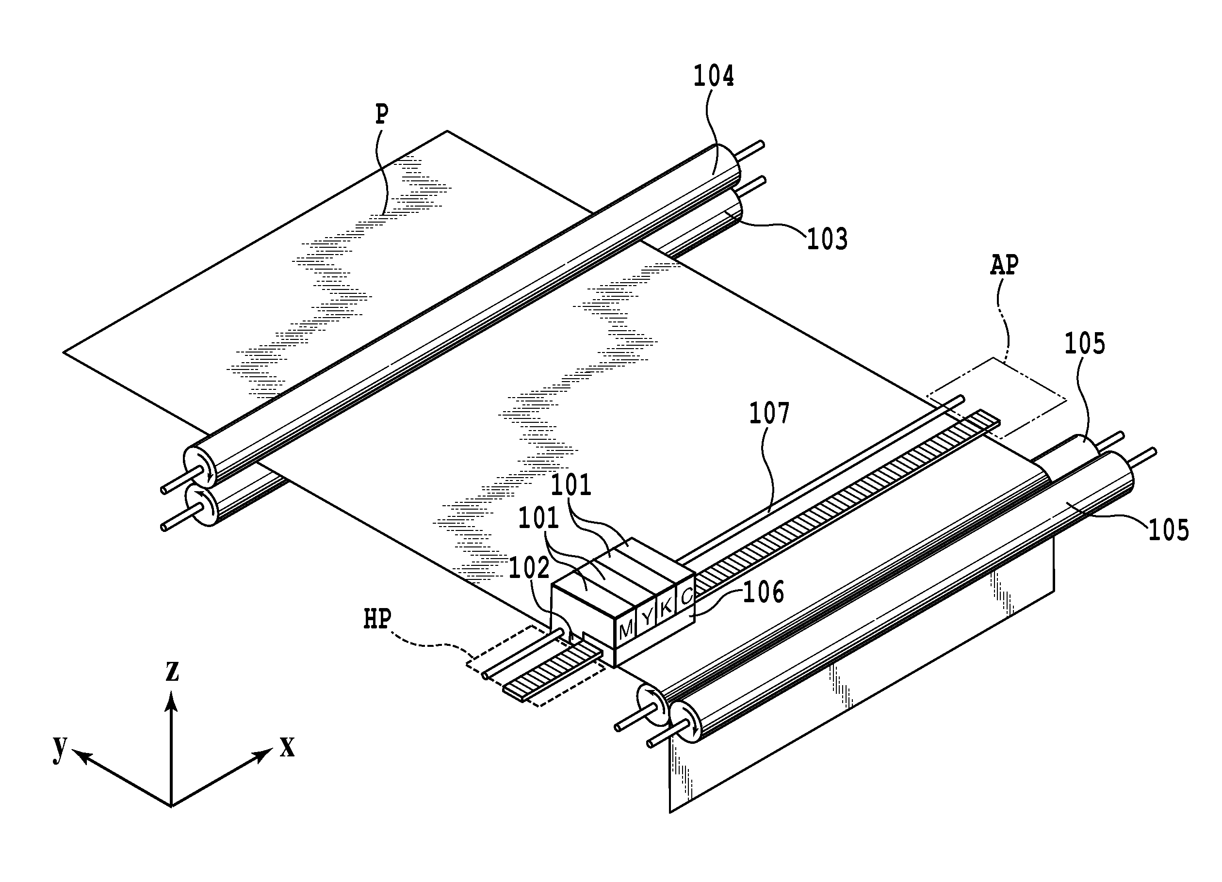
[0045]FIG. 6 is a perspective view of the schematic configuration of the ink jet printing apparatus of a first embodiment of the present invention. In FIG. 6, 101 denotes ink tanks, and the ink tanks 101 respectively store magenta (M), yellow (Y), black (K) and cyan (C) ink. The ink that is stored in the ink tanks 101 is supplied through ink supply paths (not shown) to the corresponding print heads 102. The ink tanks 101 and the print heads 102 are mounted on a carriage 106 and accordingly can be moved along the guide rail 107 in the direction indicated by the X arrow and in the direction opposite thereto. This print head unit (including the ink tanks 101, print heads 102 and carriage 106) stops at the home position HP at non-printing times. Movement (scanning) occurs in the direction indicated by the X arrow, ink is ejected from the print heads 102 while this movement occurs, and printing is performed. When the carriage 106 is moved to the away position AP, which is the reference p...

second embodiment

[0075]The second embodiment of the present invention is not configured, like the first embodiment, to perform printing by large and small drops, but rather is concerned with a configuration that uses dark and light ink in performing printing.

[0076]FIG. 17 is a schematic view of the ejection port surface of the print heads employed in the ink jet printing apparatus of the present embodiment. In the present embodiment, in addition to the ink print heads for 4 colors of Y, M, C and BK used in the above described first embodiment, in regard to cyan and magenta, print heads of light magenta (LM) ink and a light cyan (LC) ink having a weak color concentration of dye or pigment are also used. The ejection volume of a single ejection port is 4 pl in all of the print heads. Because C ink and M ink generally have a high dot contrast, in order to improve graininess, dots with a small ejection volume are used as in the first embodiment described above, or, as in the present embodiment, ink with...


PUM


Abstract

Through the use of a mask with an appropriate pattern, depending on dot size or density, in an in jet printing apparatus, image defects caused by conveyance distance errors are suppressed. More concretely, at the masking unit A an interlaced mask pattern is used and a masking process is performed with respect to 2 pl dot data obtained from the dot pattern development unit 604. On the other hand, at the masking unit B a random mask pattern is used and masking is performed with respect to 5 pl dot data. Herewith it has become possible, at all gradations, to suppress the 2 image defects, density unevenness and graininess, caused by conveyance distance errors.

Description

BACKGROUND OF THE INVENTION[0001]1. Field of the Invention[0002]The present invention relates to ink jet printing apparatuses and methods, and in particular to configurations for reducing image defects caused by errors in the conveyed distance of a print medium such as printing paper.[0003]2. Description of the Related Art[0004]It is known that in ink jet printing apparatuses black and white stripe-like density unevenness occurs in printed images, caused by errors in the conveyed distance. The conveyance mechanisms of ink jet printing apparatuses are generally composed of parts such as conveyance rollers, pinch rollers, sheet discharge rollers and spurs. These parts have variation in their dimensions. The dimensional variation of each of the parts of this kind of conveyance mechanism causes a decline in precision in conveying the print medium, and causes the occurrence of the above mentioned error in the conveyed distance. In addition to the above mentioned decline in precision in c...

Claims


Application Information

Patent Timeline
Patent Type & Authority Applications(United States)
IPC IPC(8): B41J29/38
CPCB41J2/2125G06K15/107B41J2/2132
Inventor KONNO, YUJIMURAYAMA, YOSHIAKI
Owner CANON KK
Why Eureka
Try Eureka