Motion Extraction Device and Program, Image Correction Device and Program, and Recording Medium

a technology of motion extraction and image correction, applied in the field of motion extraction device and program, image correction device and program, and recording medium, can solve the problems of increasing the size and cost of cameras, affecting the search speed, and video sending is shaken, so as to achieve the effect of shortening the search tim

Inactive Publication Date: 2011-06-09
NAT UNIV CORP SHIZUOKA UNIV
View PDF3 Cites 20 Cited by
  • Summary
  • Abstract
  • Description
  • Claims
  • Application Information

AI Technical Summary

Benefits of technology

[0017]The image change extraction device and program according to one aspect of the invention integrate the square values corresponding to all identical coordinates, where at least the first transform frame image and the second frame image overlap, so as to derive the error function; search for the minimum value of the derived error function by using the BFGS method; and extract the affine transform parameters, which are obtained at the minimum value of the error function, as the amount of change of the first frame image relative to the second frame image. Thereby, it is possible to shorten the search time at the minimum value of the error function, and thus it is possible to extract the amount of change of images constituting the moving image in real time.
[0018]The image correction device and program according to one aspect of the invention extract the amount of change of the images constituting the moving image in real time, and are thereby able to correct, in real time, the image in accordance with the amount of change.

Problems solved by technology

However, the robot equipped with a video camera may vibrate by itself or may run on a rough road surface or in a situation in which obstacles are scattered by earthquake.
Hence, shaking occurs in the video sent from the camera mounted on the robot.
For this reason, it is difficult for an operator to judge the situation in that moment, and thus the shaking is likely to have an influence on the operation based on the screen-sick.
This causes an increase in the size and cost of cameras.
However, since the moving images have a large volume of data, when the images are processed, there is a large load on the CPU (Central Processing Unit).
Thus, it is difficult to perform processing in real time.

Method used


Image

  • Motion Extraction Device and Program, Image Correction Device and Program, and Recording Medium
  • Motion Extraction Device and Program, Image Correction Device and Program, and Recording Medium
  • Motion Extraction Device and Program, Image Correction Device and Program, and Recording Medium

Examples


first embodiment

Configuration of Image Correction Device

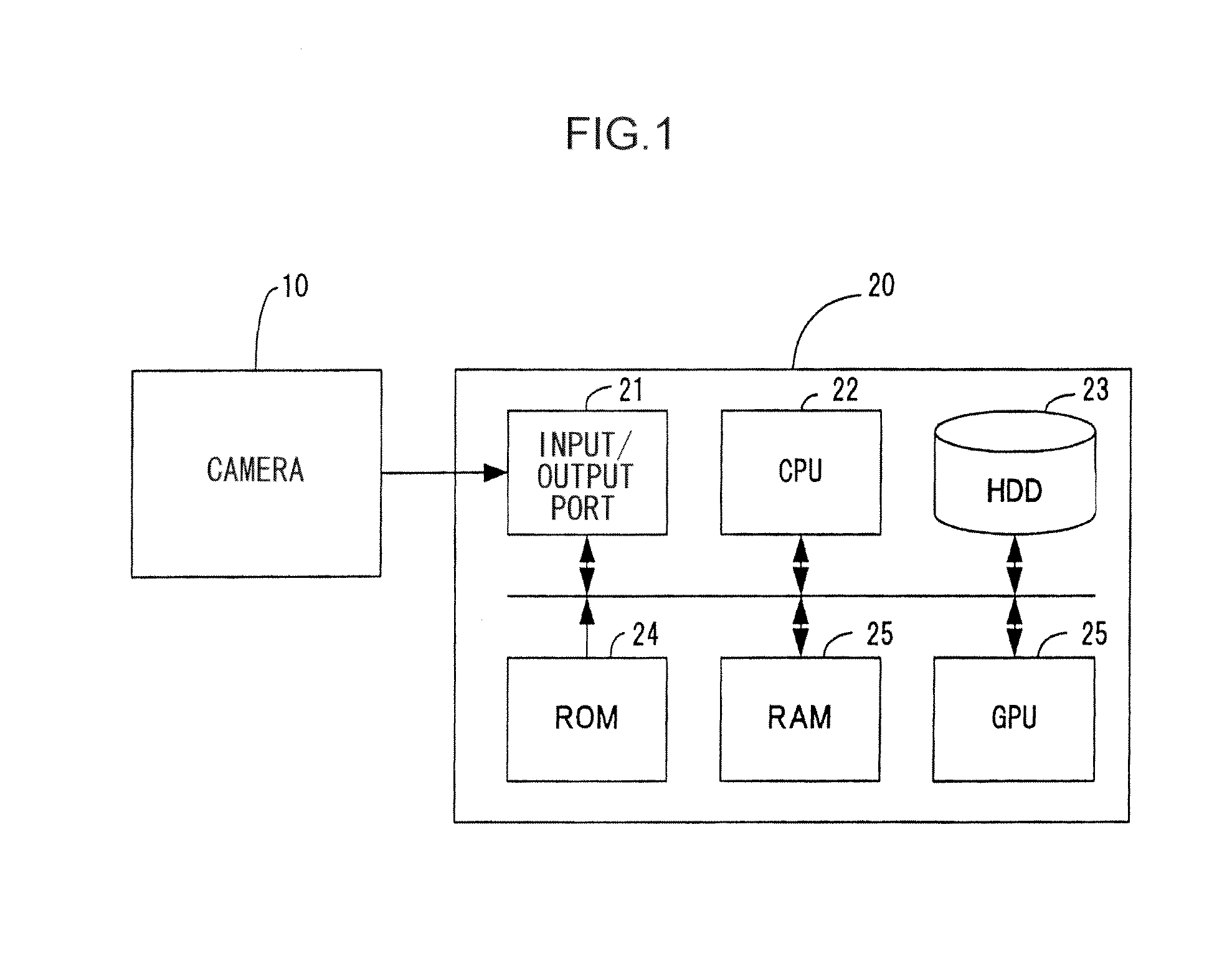
[0024]FIG. 1 is a block diagram illustrating a configuration of an image correction device according to an embodiment of the invention. The image correction device includes a camera 10 that generates an image by capturing a subject and an image processing device 20 that performs image processing so as to eliminate shaking of the image caused by the camera 10.

[0025]The image processing device 20 includes: an input / output port 21 that exchanges signals with the camera 10; a CPU (Central Processing Unit) 22 that performs calculation processing; a hard disk drive 23 that stores images and other data; a ROM (Read Only Memory) 24 that stores a control program of the CPU 22; a RAM (Random Access Memory) 25 that is a work area of the data; and a GPU 26 (Graphics Processing Unit) that performs predetermined calculation processing for image processing.

[0026]When receiving a moving image from the camera 10 through the input / output port 21, the CPU 22 seq...

second embodiment

Case of Using Other Affine Transform Parameters

[0073]Next, the second embodiment of the invention will be described. In addition, the elements common to the first embodiment will be represented by the same reference numerals and signs, and description thereof will be omitted.

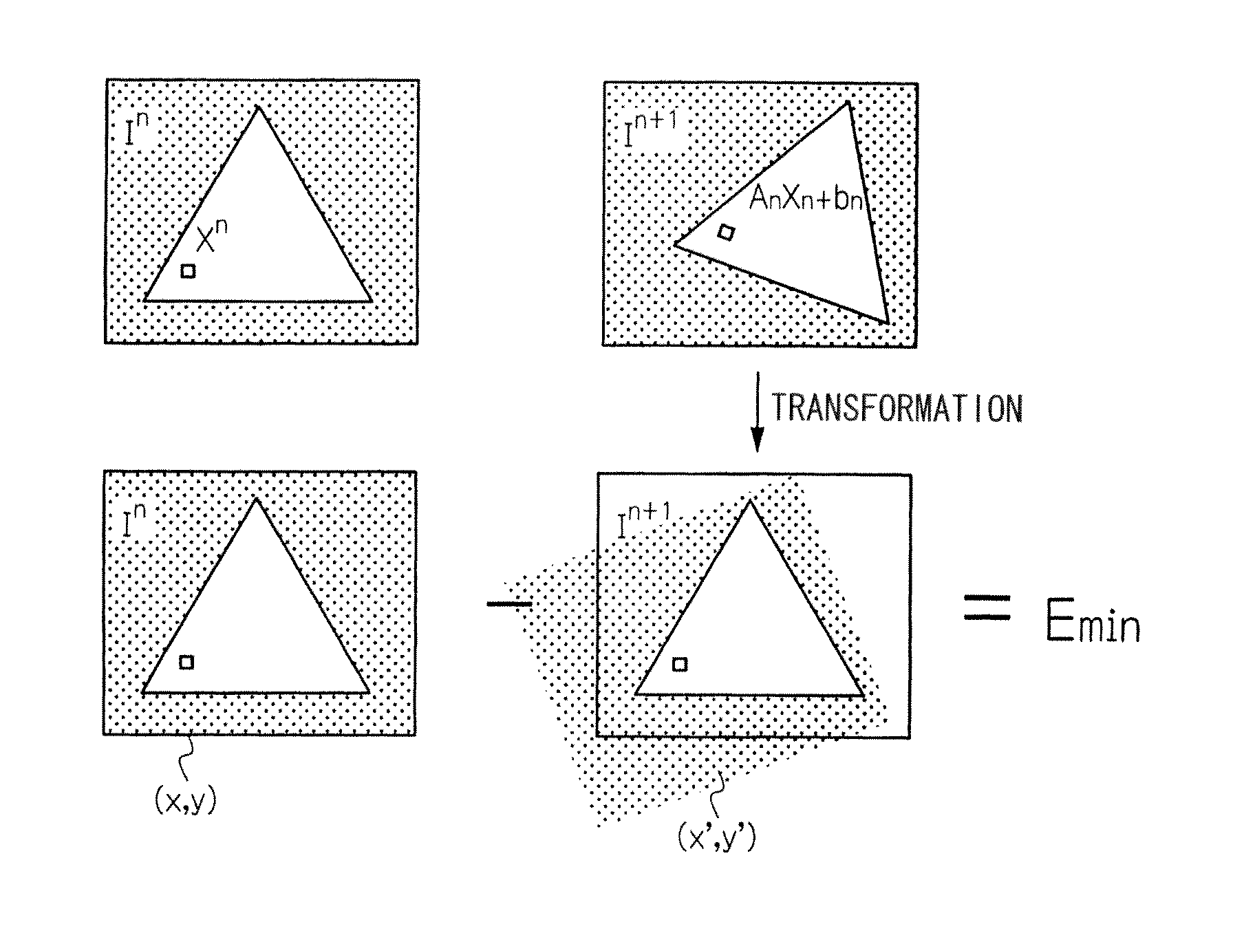
[0074]In the first embodiment, the affine transform parameters (θ, b1, and b2) of 3 variables, are used, but in the second embodiment, the affine transform parameters (θ, b1, b2, and z) of 4 variables are used. In addition, z is a parameter of a zoom direction, and represents the scale of the image. Here, the error function is represented as the following Expression (26).

NumericalExpression20E(n,n+1)=∑x∈χ(In(xn)-In+1(Ann+1xn+bnn+1))2(26)

[0075]In Expression (26), χ is a set of all coordinates on the screen plane. I(x) is a brightness value of a pixel x. In addition, when the affine transform parameters of 4 variables are used, the affine transformation is represented as the following Expression (27).

NumericalExpr...


PUM


Abstract

An image correction device is provided with a CPU (22). The CPU (22) calculates the square values of the differences between pixel values of a transformed frame image In+1 and pixel values of a frame image In at the identical coordinates thereof each time predetermined values are set in the amount of translation and the amount of rotation, respectively, and a first transform frame image is generated; integrates the square values corresponding to all identical coordinates, where at least the transformed frame image In+1 and the frame image In overlap, so as to derive the error function; searches for the minimum value of the derived error function by using the Broyden-Fletcher-Goldfarb-Shanno (BFGS) method; and extracts the affine transform parameters, which are obtained at the minimum value of the error function, as the amount of change of the frame image In+1 relative to the frame image In.

Description

TECHNICAL FIELD[0001]The present invention relates to a motion extraction device and program, an image correction device and program, and a recording medium.BACKGROUND ART[0002]Due to the recent progress regarding integration techniques, video cameras have become compact and cheap. Thus, generally, the video cameras have come into widespread use, and are used in various places. Particularly, in recent years, in order to promptly collect information at the time of disaster, small-size video cameras are mounted on, for example, remote-control rescue robots such as a robot for searching for victims of disaster in a location where people cannot approach and an unmanned helicopter for checking the disaster situation from the air.[0003]However, the robot equipped with a video camera may vibrate by itself or may run on a rough road surface or in a situation in which obstacles are scattered by earthquake. Hence, shaking occurs in the video sent from the camera mounted on the robot.[0004]For...

Claims


Application Information

Patent Timeline
Patent Type & Authority Applications(United States)
IPC IPC(8): G06K9/46
CPCG06T5/50G06T7/20G06T2207/10016H04N5/77H04N5/144H04N5/23248G06T2207/20221H04N23/68
Inventor MIURA, KENJIROTAKAHASHI, KENJI
Owner NAT UNIV CORP SHIZUOKA UNIV
Why Eureka
Try Eureka