Medical inspection device

a medical inspection and device technology, applied in the field of medical inspection devices, can solve the problems of eye strain on the user, unsatisfactory observation methods, and other inconveniences, and achieve the effect of reducing manufacturing costs and convenient repair and maintenan

Inactive Publication Date: 2011-06-09
APPLE BIOMEDICAL
View PDF9 Cites 43 Cited by
  • Summary
  • Abstract
  • Description
  • Claims
  • Application Information

AI Technical Summary

Benefits of technology

Examples of the present invention provide a medical inspection device, which comprises a body and at least one inspection module, where each of the at least one inspection module has a configuration, different from one another, suitable for entering the cavity of a particular organ. At any given time, one of the at least one inspection module can be detachably coupled to the body of the medical inspection device, so as to allow more convenient repair and maintenance of the medical inspection device and a wider variety of applications of the medical inspection device.
Some examples of the present invention also provide a medical inspection device, which has a light source settled at an end of its speculum portion, so as to save the use of any additional light pipe that is required in the prior art devices, thereby reducing the manufacturing cost.

Problems solved by technology

This can probably bring eyestrain to the user, and thus is not an ideal way to make observations.
Besides, in use of the conventional hand-held examining device, additional light sources are usually required to illuminate the dark interior of organs for clear observation, thus resulting in another inconvenience.
Consequently, the correctness of anamneses can be deteriorated if any inaccuracy exists in such sketches.
However, since the medical inspection device A10 is integrally formed, it is impossible to detach the speculum portion A14 for separate disinfection, thus being very inconvenient.
Besides, the light pipe A46 itself increases the overall manufacturing cost.
The cost for obtaining all the devices may be very high.

Method used


Image

  • Medical inspection device
  • Medical inspection device
  • Medical inspection device

Examples


Embodiment Construction

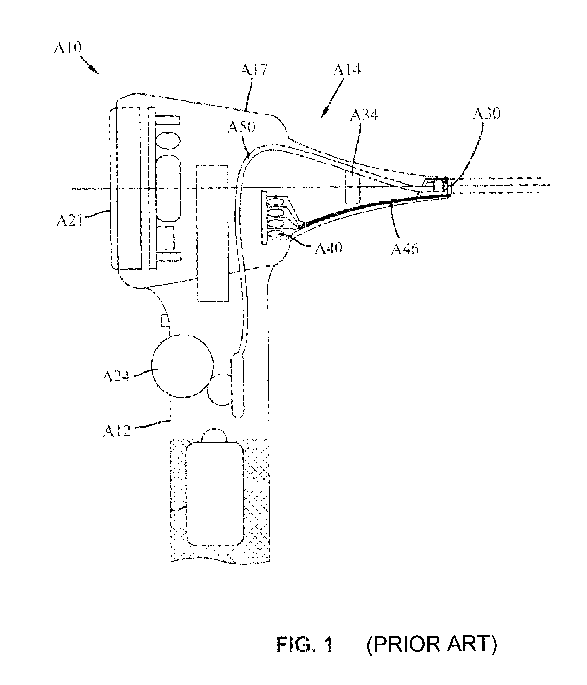
To achieve the foregoing objectives and effects, the inventor of the present invention makes improvement to the conventional medical inspection device, by configuring the inspection module as a unit detachable from other components of the medical inspection device, and rearranging the internal components, so as to excogitate an improved medical inspection device of the present invention. Hereinafter, six preferred embodiments of the medical inspection device of the present invention will be described in detail so as to illustrate the structural and technical features of the present invention.

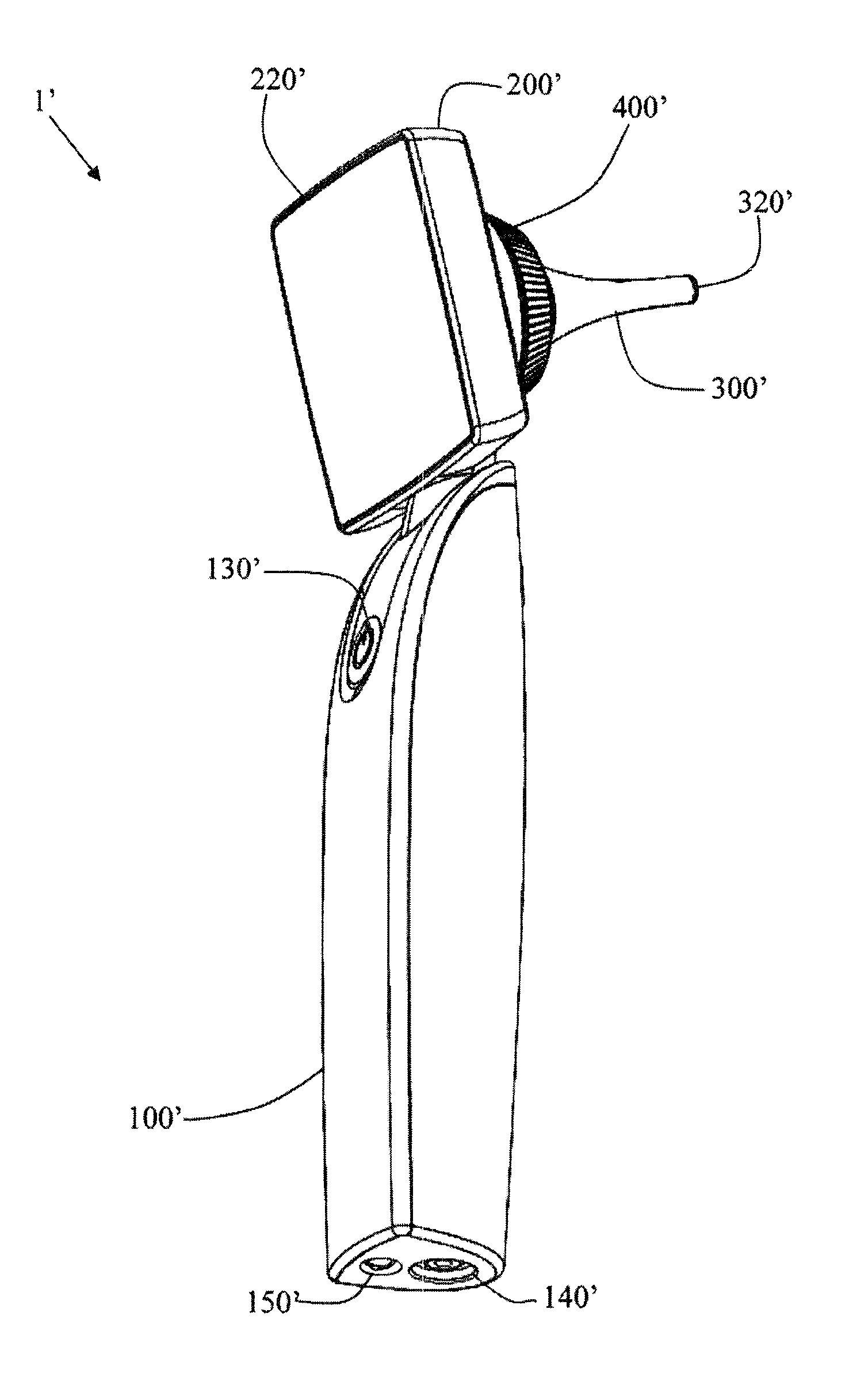
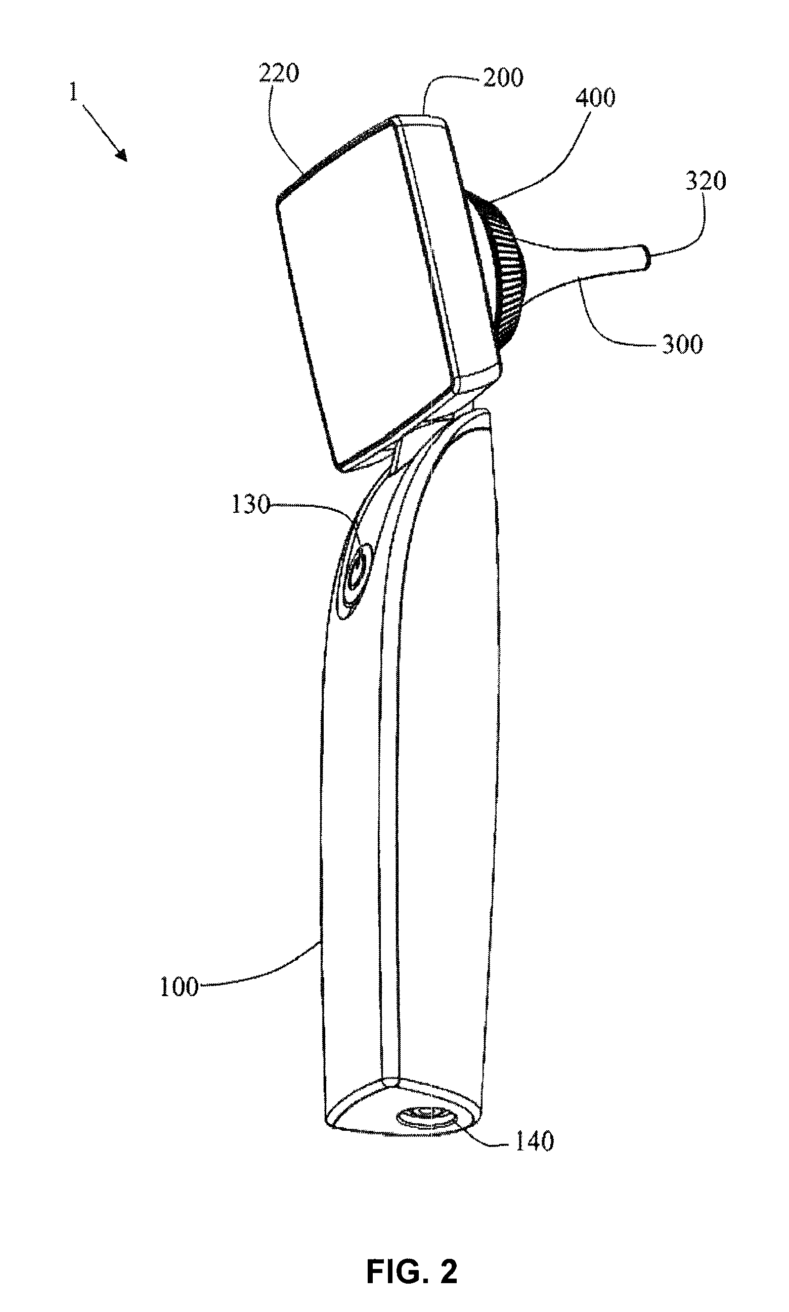
FIGS. 2-6 show a medical inspection device according to a first preferred embodiment of the present invention. FIG. 2 is a perspective view of a medical inspection device according to a first preferred embodiment of the present invention. The first preferred embodiment of the present invention primarily comprises a hand-held portion 100, a display portion 200, an inspection module 300, and a fas...


PUM


Abstract

An improved medical inspection device comprises a hand-held module, a display module, coupled to the hand-held module, a first circuit module electrically connected to the display module, and an inspection module. The display module includes an image display module, settled on a first surface of the display module, for displaying a video signal received by the display module. The inspection module is detachably coupled to the display module and comprises an inspection portion arranged at a front end of the inspection module. The inspection portion comprises a lens for taking an image of an external target object, an image sensing unit for receiving the image taken by the lens and converting the image into a video signal, a light source for emitting and projecting a light onto the target object, and a second circuit module configured to be capable of being electrically connected to the first circuit module and transmit the video signal from the image sensing unit to the display module.

Description

BACKGROUND OF THE INVENTION1. Technical FieldThe present invention relates to a medical inspection device, and more particularly, to an improved medical inspection device including a hand-held portion, a display portion, and a detachable inspection module.2. Description of Related ArtIt is common that doctors use conventional hand-held examining devices for otologic, peroral or nasal endoscopy to facilitate diagnosing patients. Such a conventional hand-held examining device is configured like a magnifying glass, having a grip shank and an observing part. The observing part has its front end formed tapered for easily entering an organ to be examined. At the distal end of the tapered part, there is a lens for magnifying an image of the interior of organs so as to facilitate a doctor's diagnosis.However, in use of the conventional hand-held examining device, to observe the magnified image, the user (i.e. the doctor) has to approach his / her eye to the observing part to look steadily at ...

Claims


Application Information

Patent Timeline
Patent Type & Authority Applications(United States)
IPC IPC(8): A61B1/233
CPCA61B1/233A61B1/227A61B1/00052A61B1/00108
Inventor HUANG, TZAI-KUN
Owner APPLE BIOMEDICAL
Why Eureka
Try Eureka