Field bus system

a field bus and bus system technology, applied in the field of field bus systems, can solve problems such as control problems, software updating methods that cannot be handled, and other problems

Inactive Publication Date: 2011-06-09
YAMATAKE HONEYWELL CO LTD
View PDF1 Cites 21 Cited by
  • Summary
  • Abstract
  • Description
  • Claims
  • Application Information

AI Technical Summary

Benefits of technology

[0018]Doing so makes it possible to commence control of the operation of the field device using the updated software after validation, on the host computer side, of the validity of the updated software that has been downloaded, after downloading the updated software to the inactive memory area. In this case, the pre-update software that is stored in the active memory area is used in the period of time up until the active/inactive switching is performed, to continue the control of the operation of the field device.
[0019]Given the present invention, the controller is provided with simulating means

Problems solved by technology

However, this type of software updating method cannot handle a situation wherein one does not wish to stop the process control even though one wishes to update the software.
However, in the method wherein the two memory areas are used, as set forth above, between downloading and

Method used


Image

  • Field bus system
  • Field bus system
  • Field bus system

Examples


Embodiment Construction

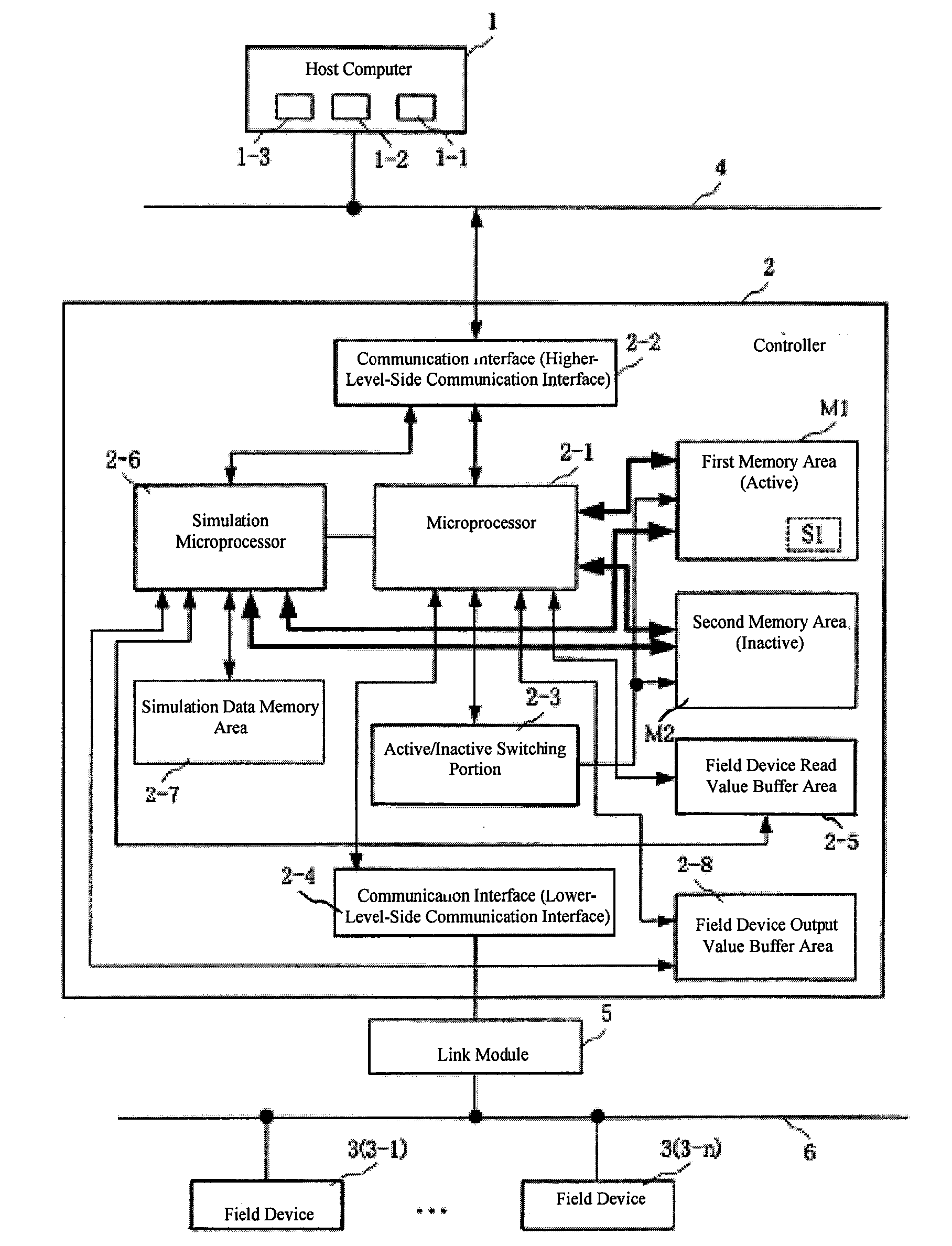
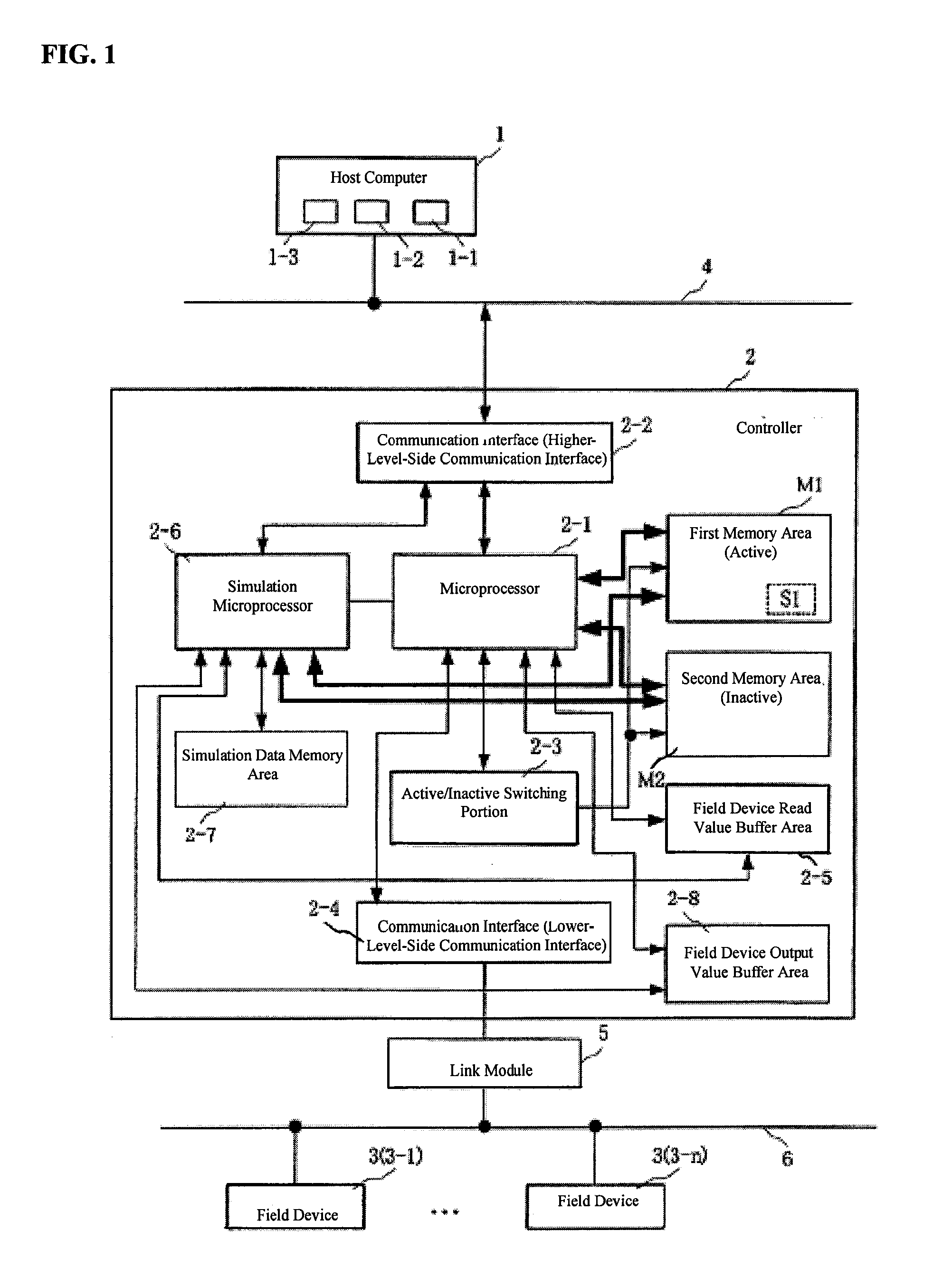
[0032]A form for embodying the present invention will be explained in detail below based on the drawings. FIG. 1 is a diagram illustrating the critical components of an example of a field bus system. In this figure, codes that are identical to those in FIG. 11 and FIG. 12 indicate identical or equivalent structural elements as the structural elements described for FIG. 11 in FIG. 12, and explanations thereof are omitted.

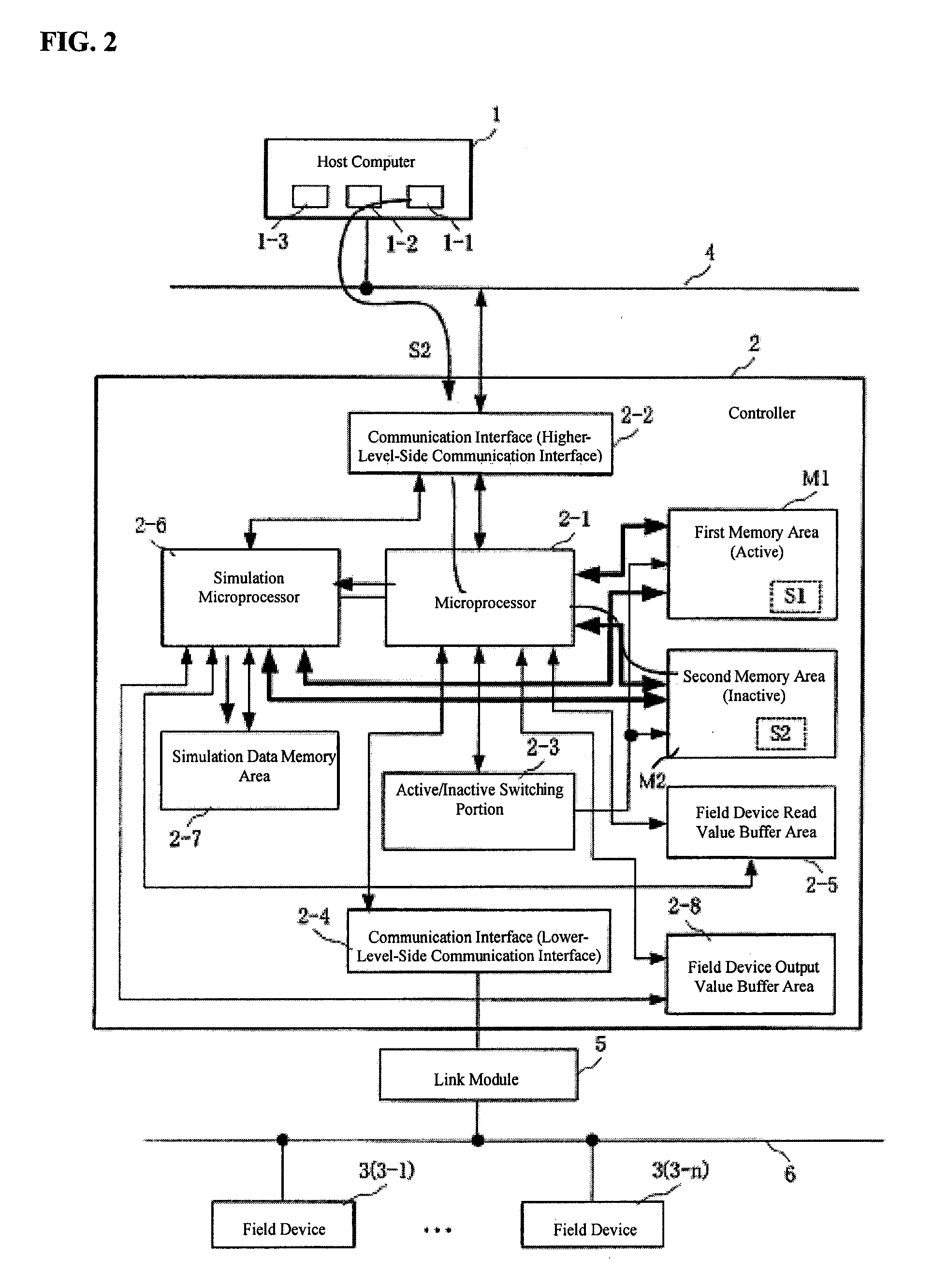
[0033]In the present form, the controller 2 includes a microprocessor 2-1; a communication interface (a higher-level-side communication interface) 2-2; an active / inactive switching portion 2-3; a communication interface (a lower-level-side communication interface) 2-4; a field device read value buffer area 2-5; a simulation microprocessor 2-6; a simulation data memory area 2-7; a field device output value buffer area 2-8; a first memory area M1; and a second memory area M2.

[0034]Note that while in the present example two microprocessors are provided, that is, the mic...


PUM


Abstract

A controller is provided with a first memory area and a second memory area, where a pre-update software is stored with the first memory area as the active area and an updated software is downloaded with the second memory area as an inactive memory area. A microprocessor for simulations performs a simulation of the control of the operation of a Held device using the updated software that has been downloaded. The execution status of the simulation can be monitored using a host computer. If the evaluation result of the state of execution of the simulation by an operator is “Pass,” then an activate command is sent to the controller. As a result, the active/inactive are switched in the controller.

Description

CROSS REFERENCE TO RELATED APPLICATIONS [0001]The present application claims priority under 35 U.S.C. §119 to Japanese Patent Application No. 2009-275352, filed Dec. 3, 2009, which is incorporated herein by reference.FIELD OF THE TECHNOLOGY [0002]The present invention relates to a field bus system for controlling a transmitting device for temperature, pressure, flow rate, or like, and a field device, such as a valve operating device, using a controller.BACKGROUND OF THE INVENTION [0003]Conventionally, this type of field bus system has been provided with a host computer, a controller that is connected through a communication line to the host computer, and a Held device that is controlled by the controller, where software for controlling the field device is downloaded from the host computer to the controller.[0004]FIG. 11 illustrates the structure of the critical components in a conventional field bus system, In the drawing: 1 is a host computer; 2 is a controller; and 3-1 through 3-n...

Claims


Application Information

Patent Timeline
IPC IPC(8): G06F9/44
CPCG05B19/0426G05B2219/23445G05B2219/23324G05B2219/23217
Inventor FURUSAWA, NAOKI
Owner YAMATAKE HONEYWELL CO LTD
Why Eureka
Try Eureka