
Feedback-Directed Call Graph Expansion

a call graph and expansion technology, applied in computing, instruments, electric digital data processing, etc., can solve the problems of sheer scale of large programs, many real-world programs that challenge wp analysis, and the exponential explosion of wp analysis

Inactive Publication Date: 2011-06-09
IBM CORP +1
View PDF5 Cites 34 Cited by
  • Summary
  • Abstract
  • Description
  • Claims
  • Application Information

AI Technical Summary

Benefits of technology

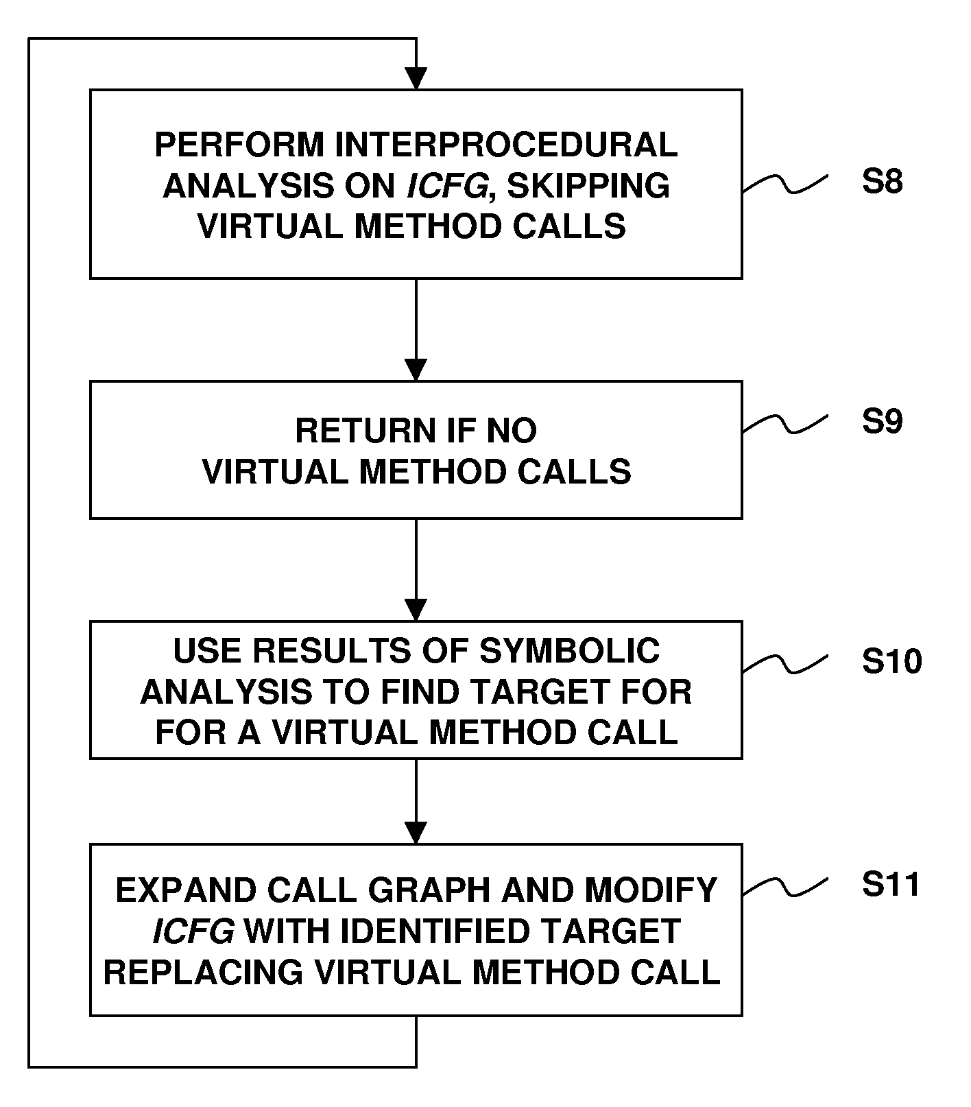
[0008]A technique for implementing feedback-directed call graph expansion is disclosed. According to an example embodiment, the technique includes performing symbolic analysis on an interprocedural control flow graph representation of software code while skipping over a virtual meth...

Problems solved by technology

Real-world programs present many challenges for wp analysis.
One problem arises from the sheer scale of large programs.
Even in loop-free programs, wp analysis faces an exponential explosion due to the number of distinct paths through the program.
In straight-line code alone, handling language features such as aliasing and type tests can require logical disjunctions, another source of state explosion.
Procedure calls further exacerbate these difficulties and introduce entirely new challenges stemming from the need to generate a call graph for interprocedural analysis.
This is especially problematic for large object-oriented libraries and frameworks.
Unfortunately, standard call graph construction algorithms face myriad difficulties disambiguating virtual calls in real-world libraries, due to the scale of the programs, unknown aliasing that clients might establish, and dynamic language features like reflection.

Method used


Image

  • Feedback-Directed Call Graph Expansion
  • Feedback-Directed Call Graph Expansion
  • Feedback-Directed Call Graph Expansion

Examples


example machine

Environment

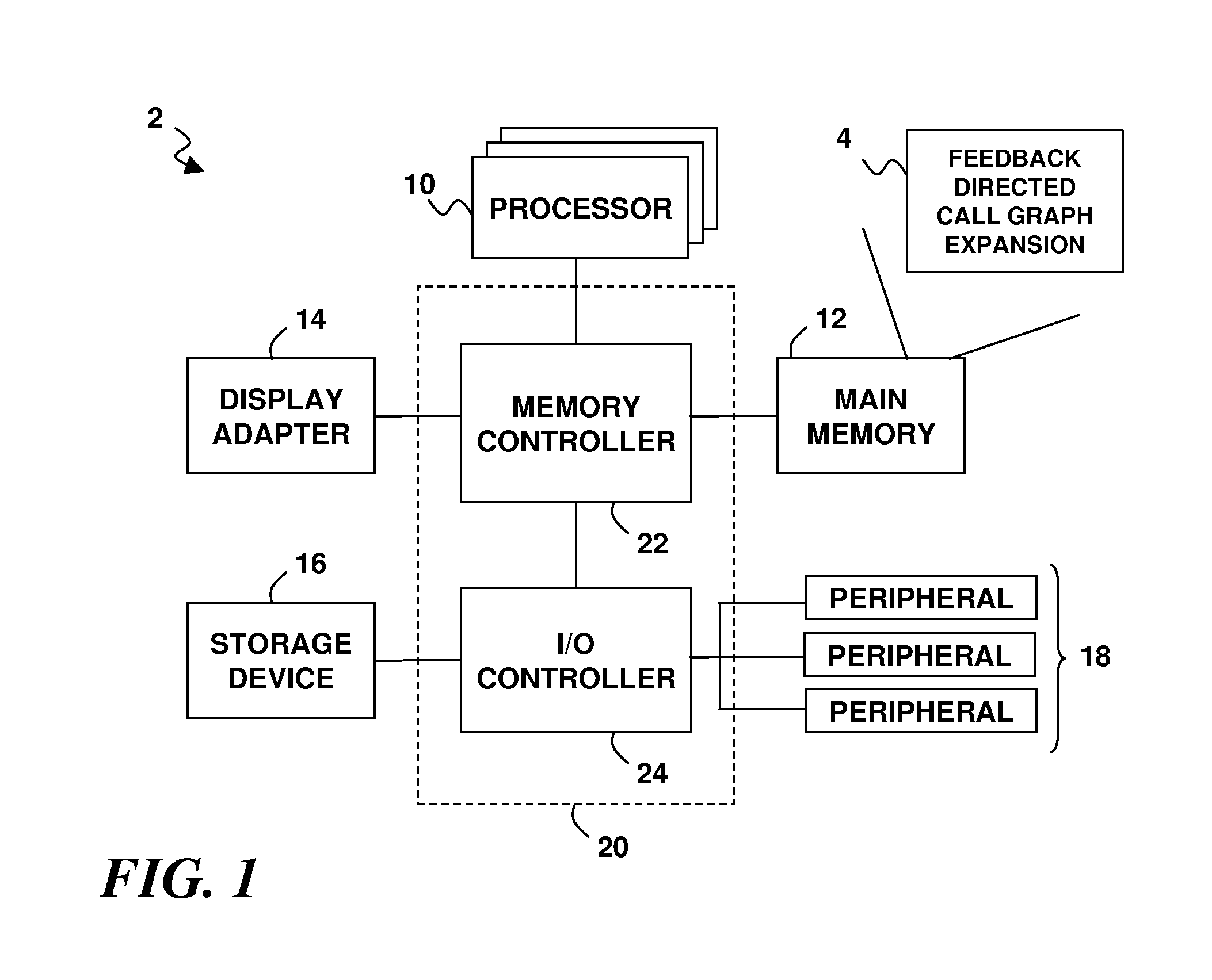
[0021]Turning now to the figures, wherein like reference numerals are used to represent like elements in all of the several views, FIG. 1 illustrates an example machine environment that may be used to perform software analysis as disclosed herein. In particular, an example computing system 2 is shown. The system 2 supports the execution of machine logic 4, which in turn controls the system 2 to perform wp analysis using a technique that will be referred to herein as feedback-directed call graph expansion. The system 2 may include one or more processors 10 that operate in conjunction with a main memory 12. As used herein, the term “processors” includes, but is not necessarily limited to, single-threaded or multi-threaded CPUs (Central Processing Units) within single-core or multi-core processor devices (each core being considered a CPU) that are designed to execute program instruction logic, such as software or firmware. The memory 16 may comprise RAM (Random Access Memory...


PUM


Abstract

A technique for feedback-directed call graph expansion includes performing symbolic analysis on an interprocedural control flow graph representation of software code, skipping over a virtual method call in the control flow graph, using information obtained from the symbolic analysis as feedback to identify a target of the virtual method call, and iterating the symbolic analysis on a modified version of the control flow graph that associates the target with the virtual method.

Description

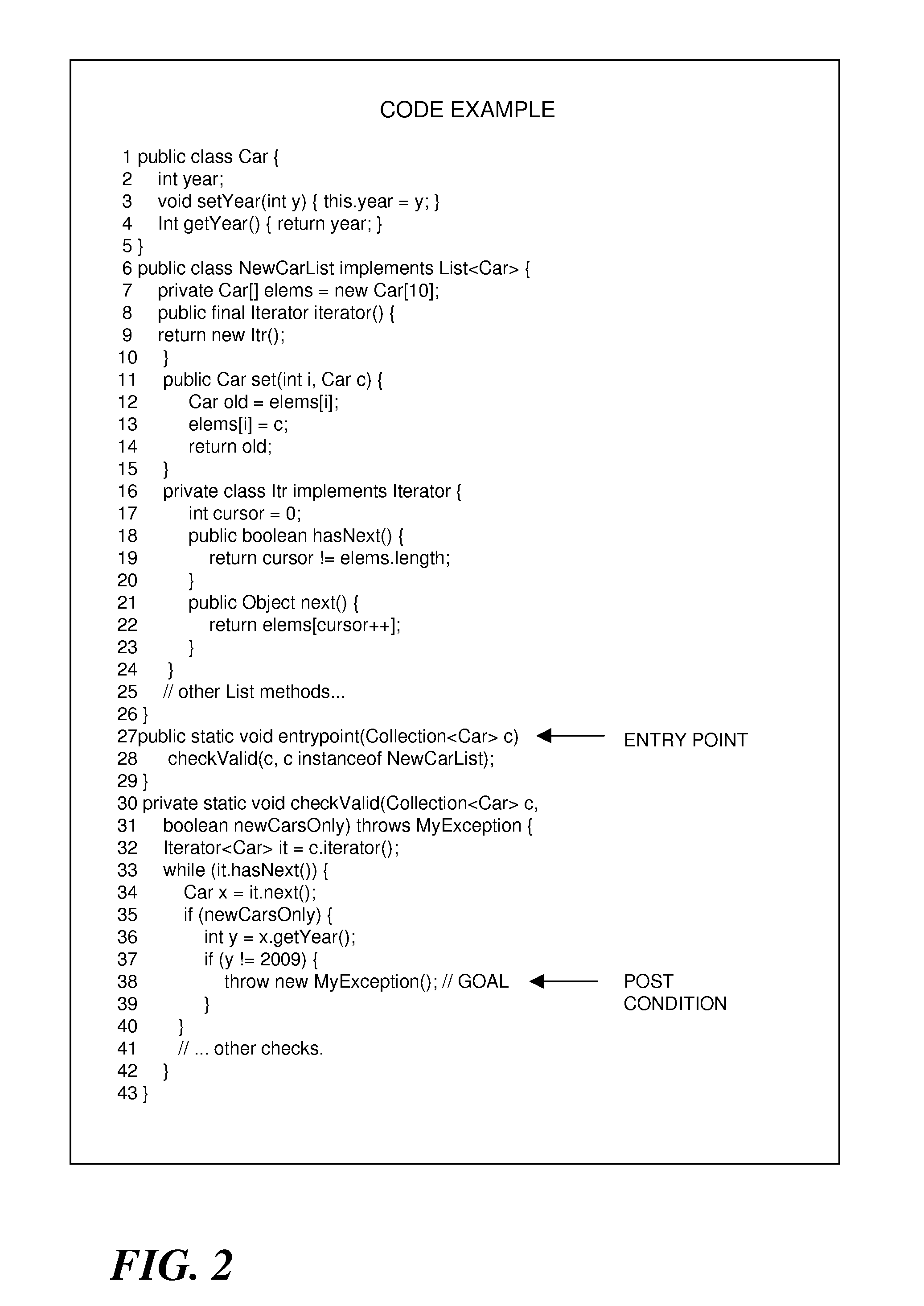
BACKGROUND[0001]1. Field of the Invention[0002]The present invention relates to computer systems and methods for evaluating, verifying and testing software program logic. More particularly, the invention concerns the use of weakest precondition analysis (or other forms of symbolic analysis) for object-oriented programs that support dynamic dispatch of functions and methods.[0003]2. Description of the Prior Art[0004]By way of background, weakest precondition (wp) analysis is a type of symbolic analysis that deals with the problem of finding a precondition φ that necessarily drives a software program from a particular entry point m to a goal state g. For example, g might represent some behavior of a library, such as a particular line of code throwing an exception. The discovered precondition φ could illustrate how to make such behavior occur when the library code is invoked. This type of analysis has numerous applications in tools for software engineering, including but not limited to...

Claims


Application Information

Patent Timeline
IPC IPC(8): G06F9/44
CPCG06F9/4431G06F8/433G06F9/4491
Inventor CHANDRA, SATISHFINK, STEPHENSRIDHARAN, MANU
Owner IBM CORP
Learn More