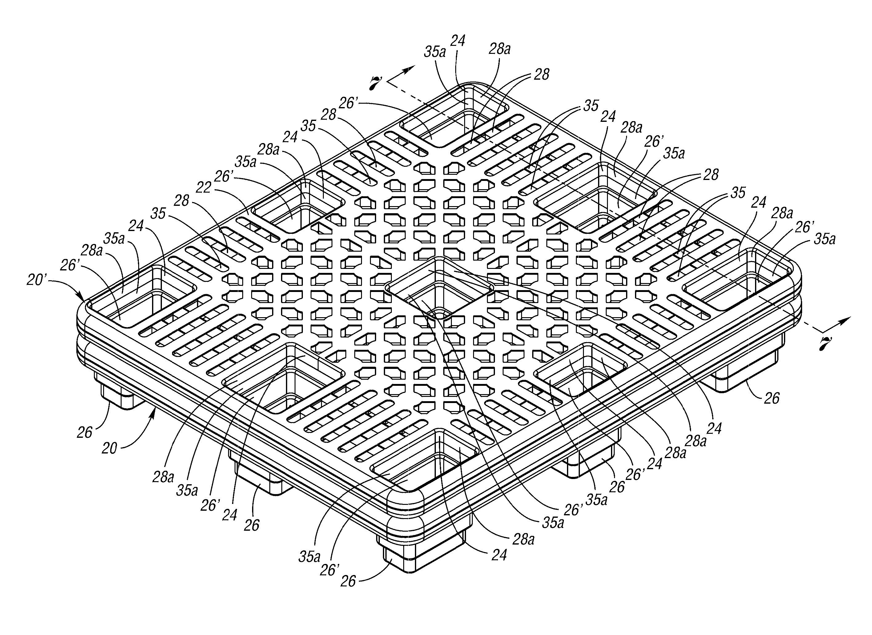
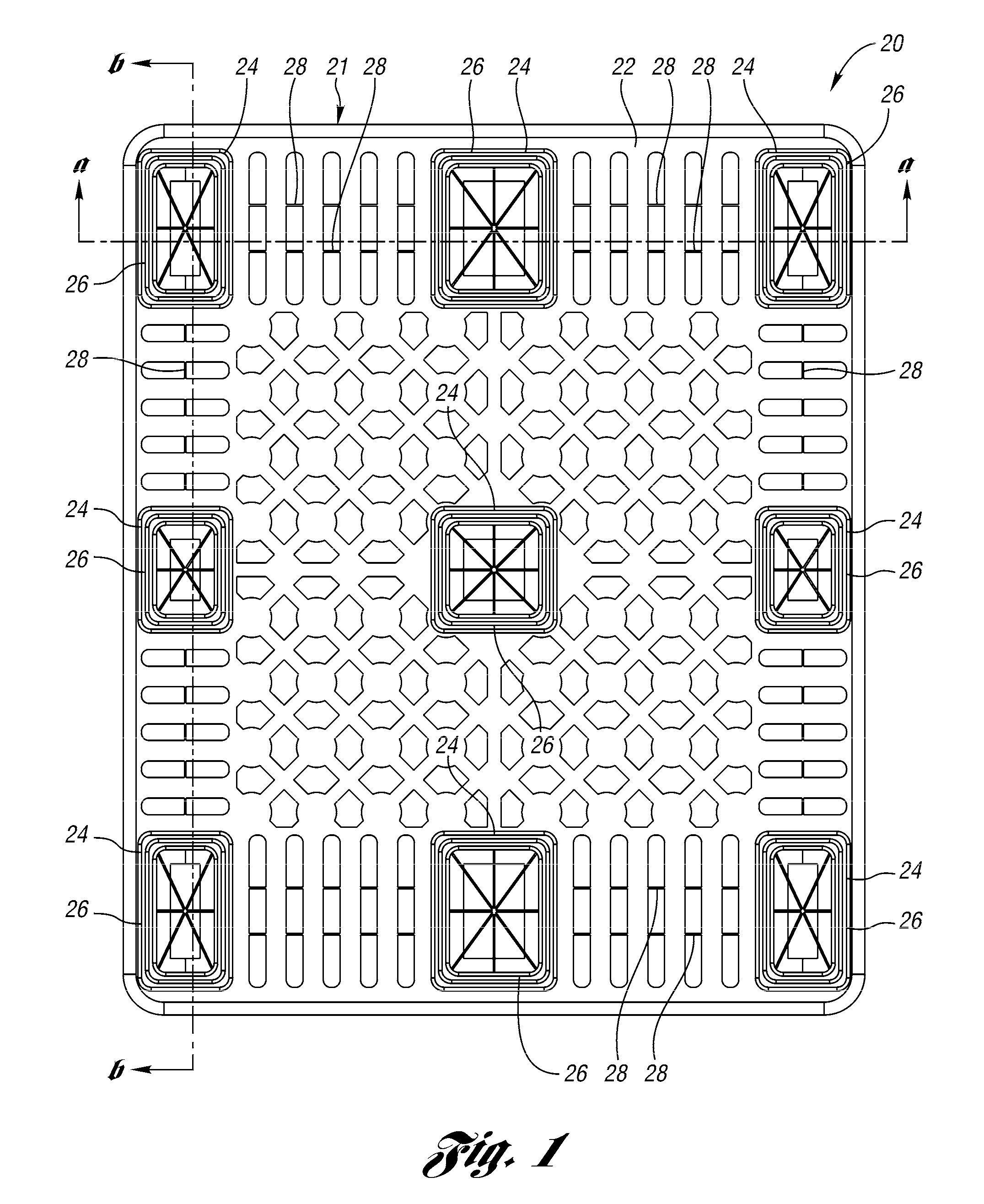
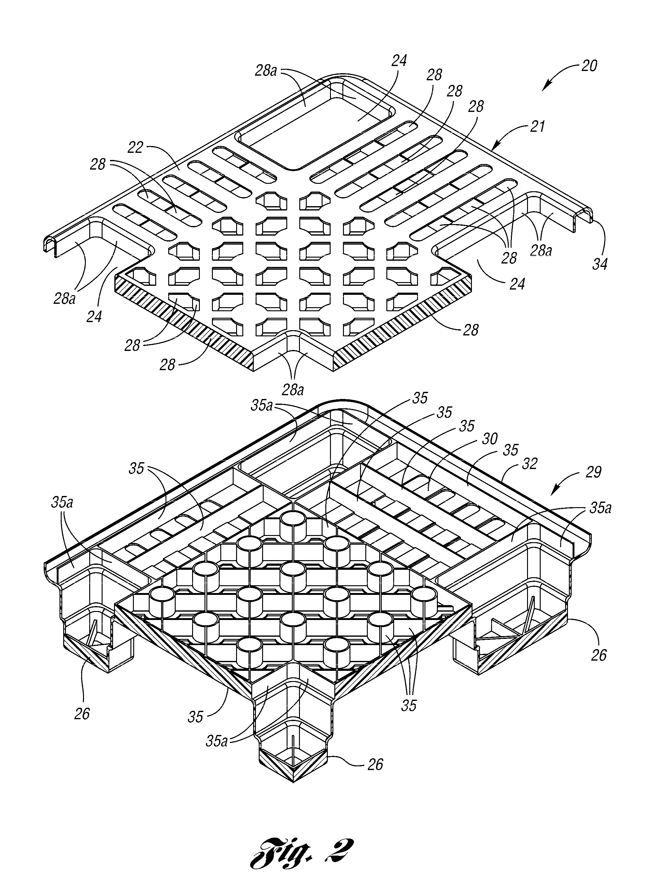
Nestable pallet

Inactive Publication Date: 2011-06-16
REHRIG PACIFIC CO INC
View PDF13 Cites 17 Cited by
  • Summary
  • Abstract
  • Description
  • Claims
  • Application Information

AI Technical Summary

Benefits of technology

The nestable pallet of the present invention provides the increased strength and durability of the box beam section in a nestable pal

Problems solved by technology

As a result, box beam sections have not been provided in nestable pallets in the prior art.
Therefore, prior art nestable pa

Method used


Image

  • Nestable pallet
  • Nestable pallet
  • Nestable pallet

Examples


second embodiment

FIGS. 8-15 show a nestable pallet 120 of the present invention. The nestable pallet 120 is generally similar to that shown in the previous Figures and will thus be described more briefly. To the extent not described below or shown in the drawings to be otherwise, the nestable pallet 120 has similar structure, features and operation to those described and shown above. Generally, structure in FIGS. 8-15 corresponding to structure in FIGS. 1-7 will be referenced with the same reference numeral with the numeral “1” prepended.

Referring to FIG. 8, the nestable pallet 120 includes an upper deck section 121 comprising an upper panel 122 having a plurality of openings 124 aligned with feet 126 extending downwardly from the pallet 120. In this embodiment, the pallet 120 includes molded handle openings 125 through the deck sections.

FIG. 9 is an exploded perspective view of the upper deck section 121 and a corresponding lower deck section 129. The lower deck section 129 includes a lower panel 1...

third embodiment

FIG. 16 is an exploded sectional view showing an alternate foot 226 in a third embodiment nestable pallet 220 of the present invention. In this pallet 220, the upper deck section 221 includes a downwardly projecting foot 227 extending from the upper panel 222 and aligned with the foot 226 of the lower deck section 229. The foot 227 of the upper deck section 221 includes upper rib sections 228 aligned with and mateable with lower rib sections extending upward from the foot 226 of the lower deck section 221.

The nestable pallets 20, 120, 220 of the present invention provide the increased strength and durability of the box beam section in a nestable pallet 20, 120, 220. Thus, the inventive pallet 20, 120, 220 has increased strength and durability in use and is also convenient to store and transport when empty.


PUM

PropertyMeasurementUnit
Lengthaaaaaaaaaa
Lengthaaaaaaaaaa
Diameteraaaaaaaaaa

Abstract

A nestable pallet includes a deck having an upper panel, a lower panel and a plurality of ribs extending perpendicularly from the upper panel to the lower panel. The upper panel further includes a plurality of openings for receiving feet of a similar pallet when nested. The lower panel further includes a plurality of feet extending downward from the deck, each foot having a cavity defined therein lined within one of the plurality of openings in the upper panel. Each cavity is configured to receive a foot from a similar pallet when nested therein.

Description

BACKGROUND OF THE INVENTIONThis invention relates to a nestable pallet for storing or transporting goods.Pallets are often to used to store and transport goods. The pallets maintain the goods at a distance above the floor such that they can be readily lifted and moved by a fork of a lift truck. Some pallets have stringers or double decks forming openings which receive the forks of the lift truck. Other pallets are nestable within one another to facilitate storage and transport when empty. Generally, nestable pallets typically have openings in their upper surface which receive corresponding shaped feet of a similar nestable pallet. Thus, the nestable pallets are easier to store and transport when empty.U.S. Pat. No. 6,283,044, assigned to the assignee of the present invention, discloses the use of box beam cross sections to provide a stronger, more durable injection molded pallet. Generally, upper and lower ribbed pallet sections are heat welded together to form the entire pallet. Th...

Claims


Application Information

Patent Timeline
IPC IPC(8): B65D19/38B65D19/00
CPCB65D19/0018Y10T29/49826B65D2519/00069B65D2519/00273B65D2519/00288B65D2519/00303B65D2519/00308B65D2519/00318B65D2519/00338B65D2519/00407B65D2519/00412B65D2519/00557B65D2519/00562B65D2519/0094B65D19/38Y10T29/4998B65D2519/00034
Inventor APPS, WILLIAM P.KOEFELDA, GERALD R.AIKEN, CYNTHIA R.
Owner REHRIG PACIFIC CO INC
Why Eureka
Try Eureka