Liquid diffuser device

a diffuser device and liquid technology, applied in the field of irrigation systems, can solve the problems of difficult control of considerable atomization of peripherally projected liquid, and inability to control and limit the rotation speed of the rotating member, so as to achieve a wider rotation of the rotating member and a longer jet

Active Publication Date: 2011-06-16
KOMET AUSTRIA GMBH
View PDF16 Cites 2 Cited by
  • Summary
  • Abstract
  • Description
  • Claims
  • Application Information

AI Technical Summary

Benefits of technology

[0016]The main object of the present invention is to obviate the above drawbacks, by providing a diffuser device that allows optimized control of the diffuser plate rotation in the various operating conditions, and can also adjust the position of the sprinkling surface relative to the water jet.
[0017]Another object of the present invention is to provide a diffuser device that can provide a wider and more uniform jet than prior art diffusers.
[0018]A further object is to provide a diffuser device that reduces liquid atomization for increased efficiency.

Problems solved by technology

A commonly recognized drawback of prior art devices is the difficulty of controlling the rotation speed of the plate to obtain as wide and uniform a jet as possible.
Furthermore, in these devices, a considerable part of the peripherally projected liquid is atomized due to the diffuser motion and evaporates before reaching the soil.
While this solution ensures rotation of the diffuser at any speed, it cannot control and limit the rotation speed of the rotating member and hence instantly adjust the water jet.
Furthermore, the presence of a gear assembly increases construction and assembly complexity and costs.
Also, since the hollow body is totally open, foreign bodies, such as sand or dust, may infiltrate the areas that support and contact the rotating member, and cause irregular operation, possibly leading to total blockage.
While this prior art solutions provides a simpler diffuser, it still cannot adjust the rotation speed and cannot prevent abnormal operation and blockage from occurring as a result of foreign bodies penetrating the areas that support the mutually contacting parts or against which they slide.

Method used


Image

  • Liquid diffuser device
  • Liquid diffuser device
  • Liquid diffuser device

Examples


Embodiment Construction

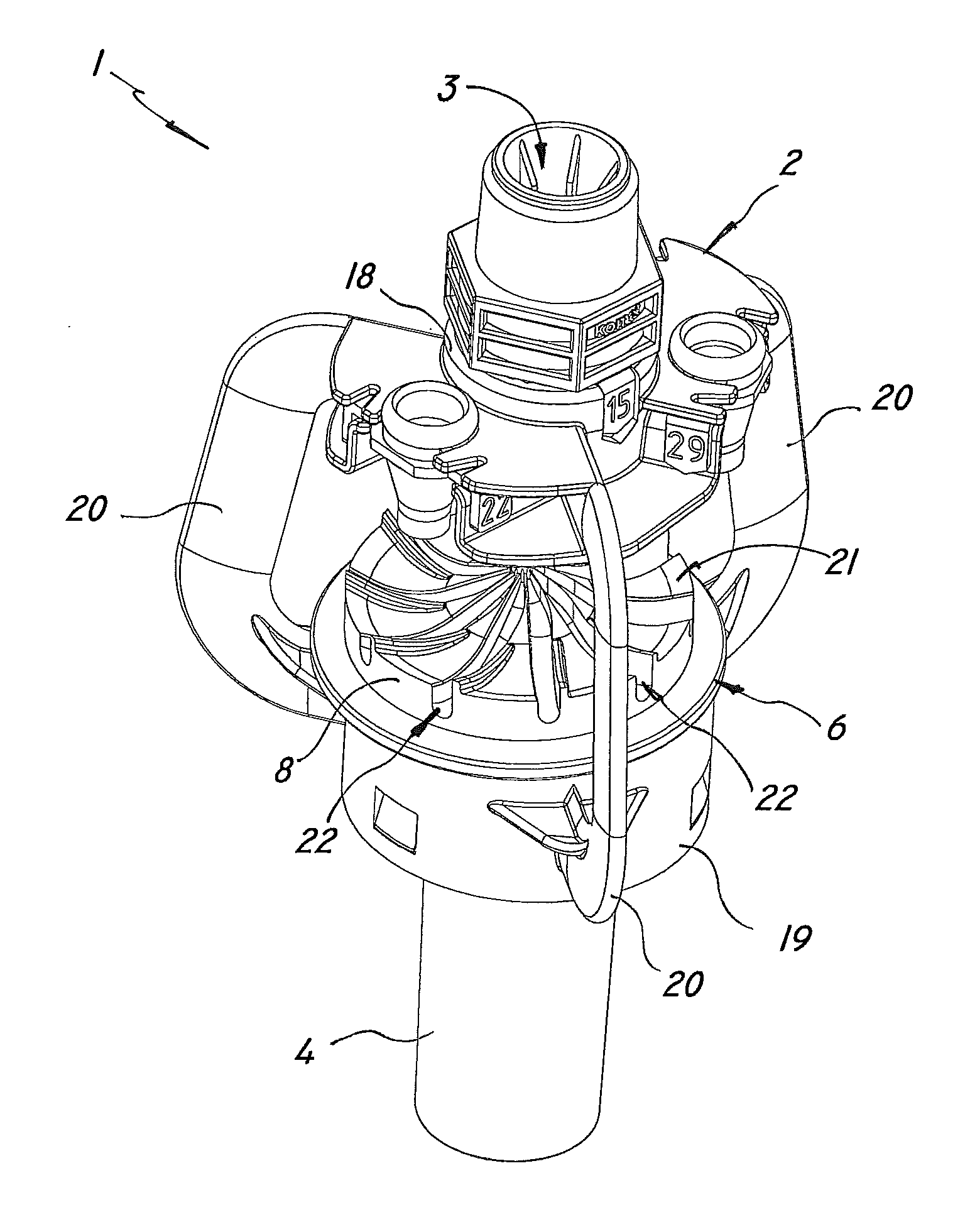
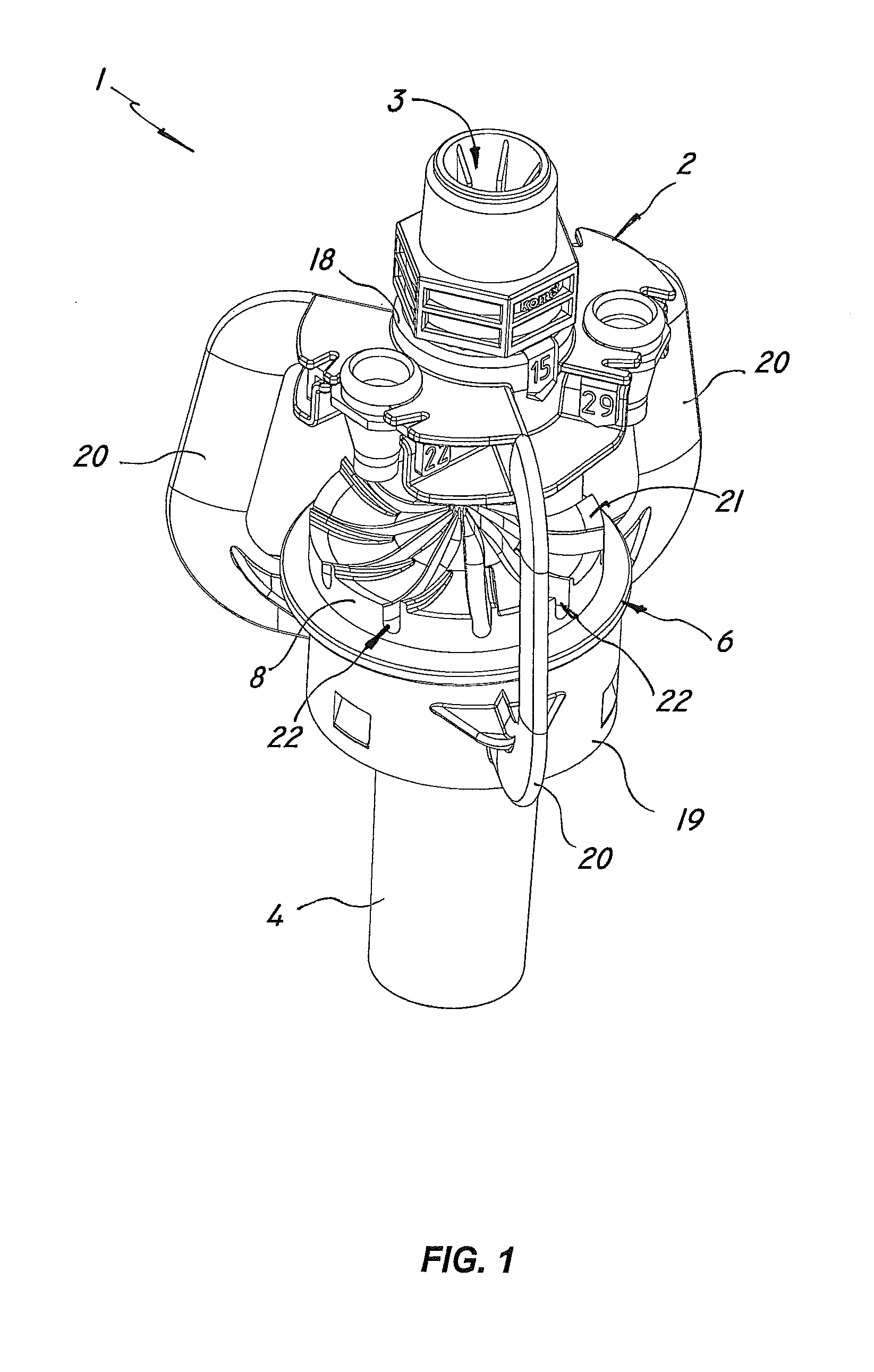
[0034]Referring to the above figures, the diffuser device of the invention, generally designated by numeral 1, may be used to distribute a liquid, e.g. water, over surfaces, possibly having a very large surface area, such as in the irrigation of agricultural areas.

[0035]For this purpose, the device 1 may be connected to a hydraulic system, not shown, for liquid delivery and may be mounted, alone or in combination with other similar devices, to a stationary or rotating support arm, also not shown, to be set at a predetermined height, according to the desired jet length.

[0036]According to the invention, a liquid diffuser device comprises a support frame 2 connectable to a liquid feeding pipe of an irrigation system and having an upper tubular passageway 3 and a lower hollow body 4 both defining a first longitudinal axis L.

[0037]The upper passageway 3 of the frame 2 is associated with a nozzle 5 for directing a liquid jet longitudinally downwards at predetermined pressure and flow rate...


PUM


Abstract

A liquid diffuser device comprises a support frame (2) with an upper tubular passageway (3) and a lower hollow body (4) defining a first longitudinal axis (L), a nozzle (5) associated with the passageway for directing a liquid jet longitudinally downwards at predetermined pressure and flow rate, a deflecting member (6) with a stem (7) held within the hollow body (4) and a deflecting plate (8) associated with the stem (7) and facing towards the nozzle (5) for deflecting the jet peripherally outwards and promoting the rotation (ω1) of the stem (7) about the first longitudinal axis (L) with a predetermined rotation speed, self-adjustment means (9) for adjusting the rotation speed of the stem, which comprise at least one elastomeric braking member (10) interposed between the stem (7) and the hollow body (4) for automatically adjusting the rotation speed of the stem (7) upon variation of pressure and flow rate of the liquid jet and for allowing even distribution of the diverted liquid.

Description

FIELD OF THE INVENTION[0001]The present invention generally finds application in the field of irrigation systems for agricultural and industrial applications, and particularly relates to a liquid diffuser device.[0002]The device will be particularly suitable for irrigation of cultivated lands and may be used alone or in combination with one or more similar devices.BACKGROUND ART[0003]Liquid diffuser liquids, particularly of the type commonly known as “sprinklers” are known to be used in irrigation systems for distributing water or other fluids, particularly for large lands.[0004]Typically, diffuser devices have a support frame which is designed to be connected to the hydraulic system and has a nozzle for directing the liquid jet to a specially shaped diffusion plate.[0005]The latter is in turn mounted to a rotating stem, which is connected to the stationary part of the frame and is rotated under jet pressure.[0006]A commonly recognized drawback of prior art devices is the difficulty...

Claims


Application Information

Patent Timeline
Patent Type & Authority Applications(United States)
IPC IPC(8): B05B3/02
CPCB05B3/003B05B3/0486B05B3/008
Inventor DRECHSEL
Owner KOMET AUSTRIA GMBH
Why Eureka
Try Eureka