Input device

a technology of input device and input body, which is applied in the direction of mechanical control device, magnetic body, instruments, etc., can solve the problems of difficult to provide tactile feeling, and achieve the effect of improving the confirmation of operation and easy confirmation of operation

Inactive Publication Date: 2011-06-16
DENSO CORP +1
View PDF14 Cites 22 Cited by
  • Summary
  • Abstract
  • Description
  • Claims
  • Application Information

AI Technical Summary

Benefits of technology

[0015]In the above structure, when the coil is energized, the core is magnetized by a magnetic field produced by the electric current passing through the coil. Thus, magnetic forces are produced between the first end surface of the core and the first opposed surface of the first magnet and between the second end surface of the core and the second opposed surface of the second magnet. The external force is applied to the operating member in a direction along an operation direction utilizing the magnetic forces. Accordingly, the user operating the operating member experiences a tactile feeling and easily confirms his/her operation.
[0016]In additi

Problems solved by technology

Therefore, it may be difficult

Method used


Image

  • Input device
  • Input device
  • Input device

Examples


first embodiment

[0044]An input device 10 according to the first embodiment is characterized by arrangement between magnets and electromagnets to which a magnetic force exerted.

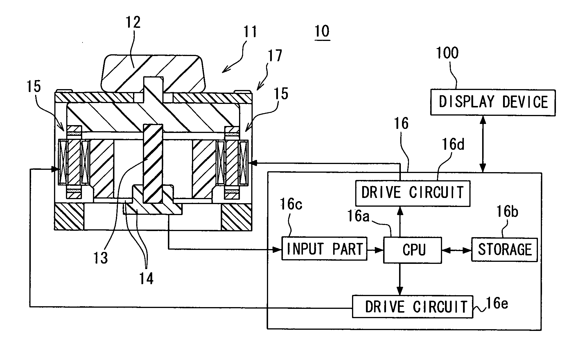
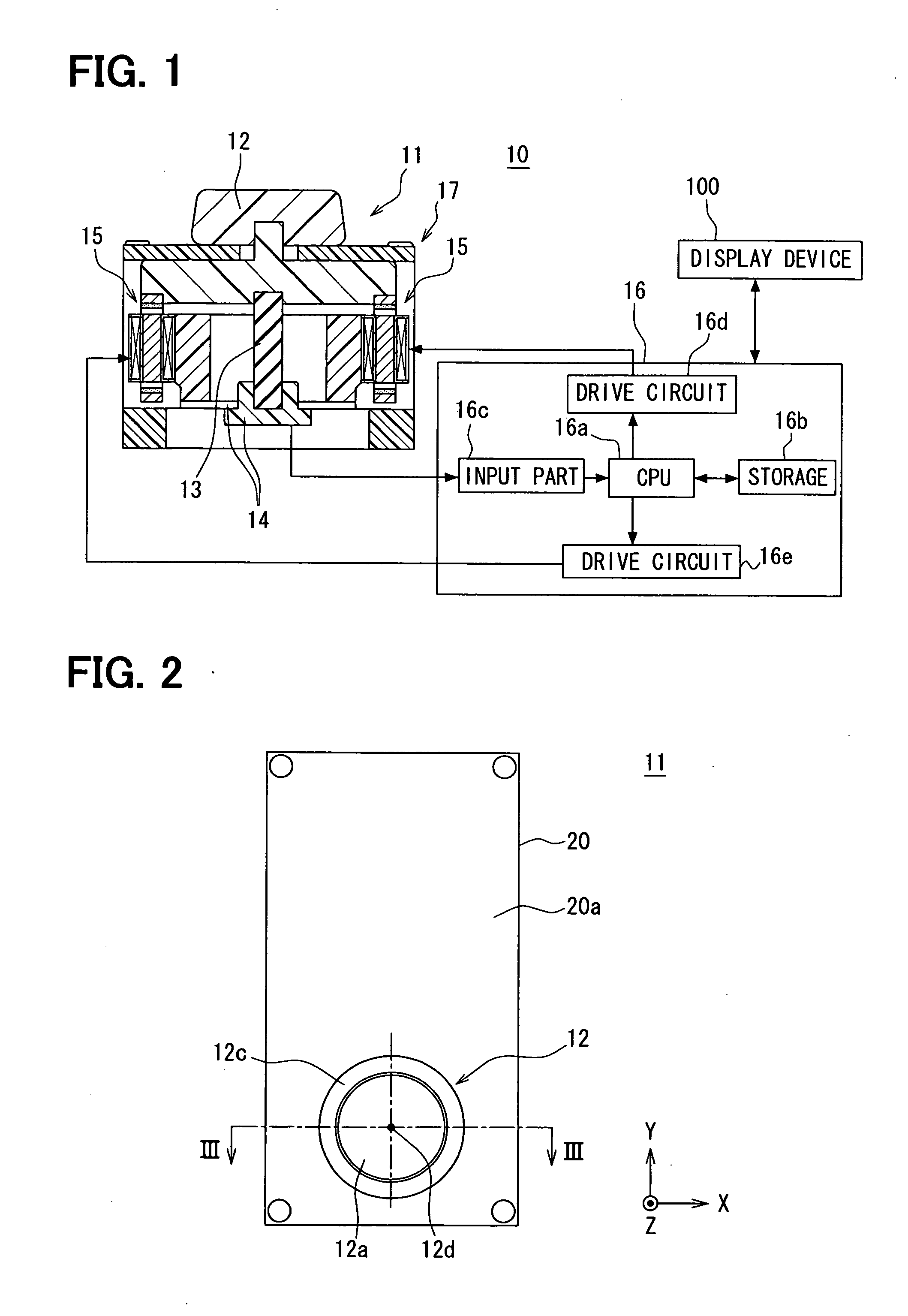
[0045]Referring to FIG. 1, the input device 10 is provided as a device for feeding information to an electronic device such as a display device 100 for a vehicle navigation system.

[0046]For example, the display device 100 has a display screen 110 shown in FIG. 7. The display screen 110 is arranged on a dashboard of a passenger compartment, at a substantially middle position with respect to a transverse direction of the vehicle.

[0047]The input device 10 has an operating member 12 to be operated by a user such as a driver. The operating member 12 is, for example, located on an upper surface of a center console beside a driver seat. Thus, a driver can operate the operating member 12 from the driver seat without largely changing his / her position.

[0048]The input device 10, as an input unit 11, includes the operating member 12 to b...

second embodiment

[0171]An input device according to the second embodiment of the present invention will be described with reference to FIGS. 10 to 11B. As shown in FIG. 10, the restoring force generating part is included in the actuator 15. That is, the input device 10 does not have the restoring force generating member 13 as an individual member. In other words, the restoring force generating part is not provided as a member separate from the actuator 15. Instead, it is configured that the actuator 15 has a function of the restoring force generating member 13.

[0172]Other structures are generally the same as the input device 10 of the first embodiment. The magnets 43, 44, 53, 54 are the permanent magnets. Here, since the restoring force generating member 13 is not provided, the detector 14 is constructed as a non-contact location information detecting part. For example, the detector 14 is constructed of a permanent magnet 14c and multiple hall devices 14d.

[0173]The permanent magnet 14c is made of a...

third embodiment

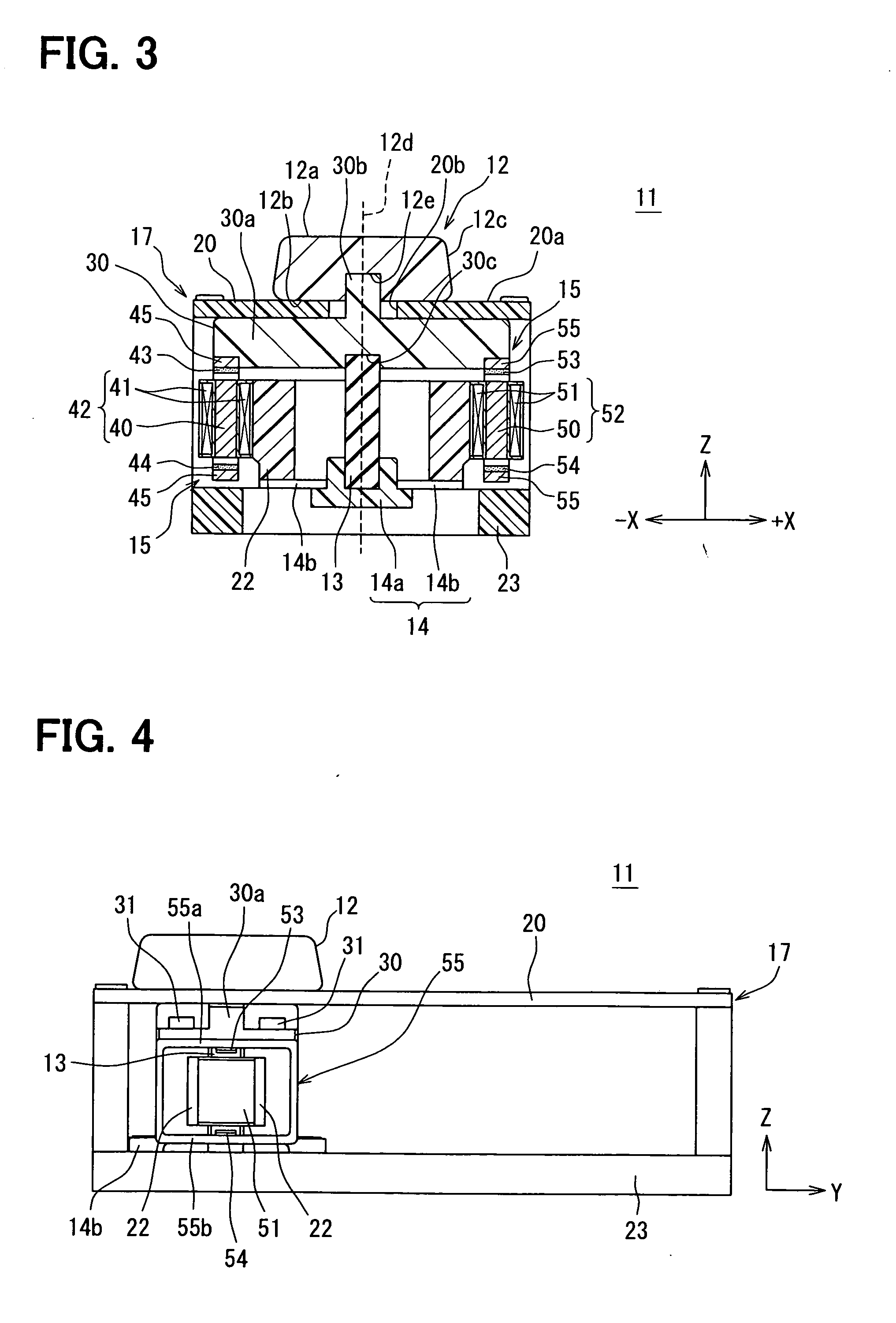
[0185]Next, an input device according to the third embodiment will be described with reference to FIGS. 12 to 14A. In the input device 10 according to the third embodiment, as shown in FIG. 12, the input unit 11 has a single electromagnet 62 and a pair of magnets 63, 64. Other structures are generally the same as the input device 10 of the first embodiment.

[0186]Similar to the electromagnets 42, 52 of the first and second embodiments, the electromagnet 62 has one core 60 and a coil 61 wound around the core 60. The core 60 has end surfaces 60a, 60b parallel to the XY plane. The core end surfaces 60a, 60b are located on opposite sides of the rotation axis 12d, at least in the stationary condition where the operating member 12 is at the stationary position.

[0187]For example, the core 60 has a generally U-shape including side portions 60c and a connecting portion 60d. The side portions 60c extend in the direction of Z axis. For example, the side portions 60c extend straightly in the dir...


PUM


Abstract

An input device includes an operating member, a restoring force generating part for automatically returning the operating member to a stationary position, a detector for detecting an operation state of the operating member, an actuator for applying an external force to the operating member and a controller for controlling the actuator. The operating member is displaceable in directions along a XY plane including an X axis and a Y axis and rotatable about a Z axis. The actuator includes a first magnet, a second magnet and an electromagnet having a core and a coil. One of the electromagnet and the first and second magnets is integrated with the operating member. At least in a stationary condition, the first magnet and the second magnet are located on opposite sides of an axis of rotation of the operating member, and are opposed to end surfaces of the core across predetermined clearances, respectively.

Description

CROSS REFERENCE TO RELATED APPLICATION[0001]This application is based on Japanese Patent Application No. 2009-281870 filed on Dec. 11, 2009, the disclosure of which is incorporated herein by reference.FIELD OF THE INVENTION[0002]The present invention relates to an input device having an operating member to be operated by a user. More particularly, the present invention relates to an input device having an operating member that is supported to be displaceable in arbitrary directions along an XY plane including a X axis and a Y axis and rotatable about a Z axis from a stationary position, and is capable of providing the user with a tactile feeling according to an operation condition by the user.BACKGROUND OF THE INVENTION[0003]An input device for inputting information to a remote electronic device, such as a display device, has been proposed. The input device has an operating member to be operated by a user. For example, the input device is employed to move a cursor such as a pointer ...

Claims


Application Information

Patent Timeline
IPC IPC(8): H01F7/00
CPCG05G5/05G05G2009/04714H01F7/08G05G2009/04781G05G2009/04766
Inventor HATANAKA, SHINJIKITAGAWA, NOZOMI
Owner DENSO CORP
Why Eureka
Try Eureka