Image forming apparatus

a technology of image forming apparatus and liquid container, which is applied in the direction of typewriters, printing, etc., can solve the problems of inability to supply ink stably and degrade the sealability of the valve member

Active Publication Date: 2011-06-16
RICOH KK
View PDF4 Cites 8 Cited by
  • Summary
  • Abstract
  • Description
  • Claims
  • Application Information

AI Technical Summary

Benefits of technology

[0009]Accordingly, embodiments of the present invention may provide a novel and useful liquid container and image forming apparatus solving one or more of the problems discussed above.

Problems solved by technology

However, in a case where the filter is simply provided at the air side opening of an air communicating path like the above-mentioned related art, foreign particles which cannot be caught by a filter member may enter the air opening path as they are so that of sealability of the valve member may be degraded.
Hence, it may not be possible to supply the ink stably.

Method used


Image

  • Image forming apparatus
  • Image forming apparatus
  • Image forming apparatus

Examples


first embodiment

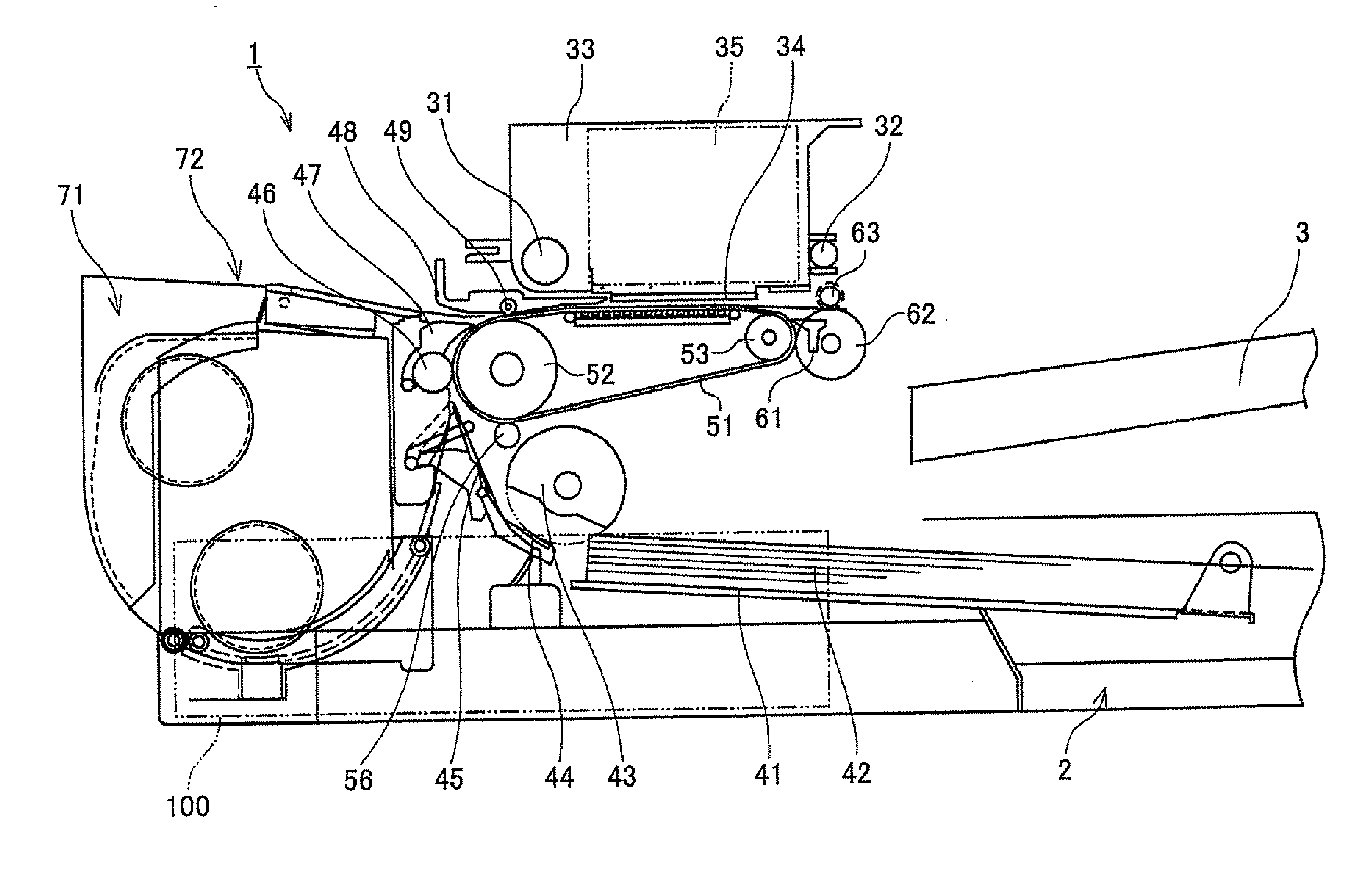
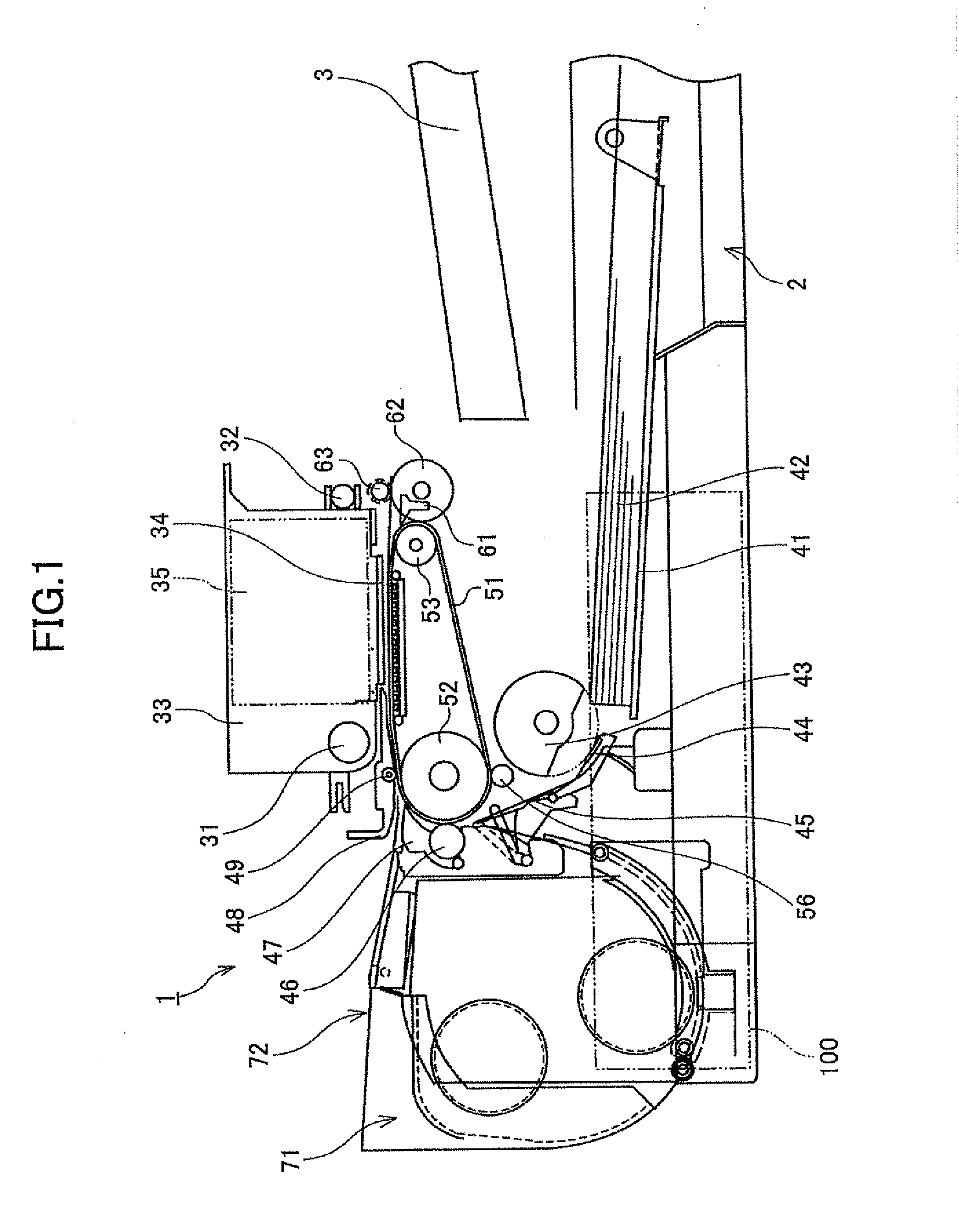
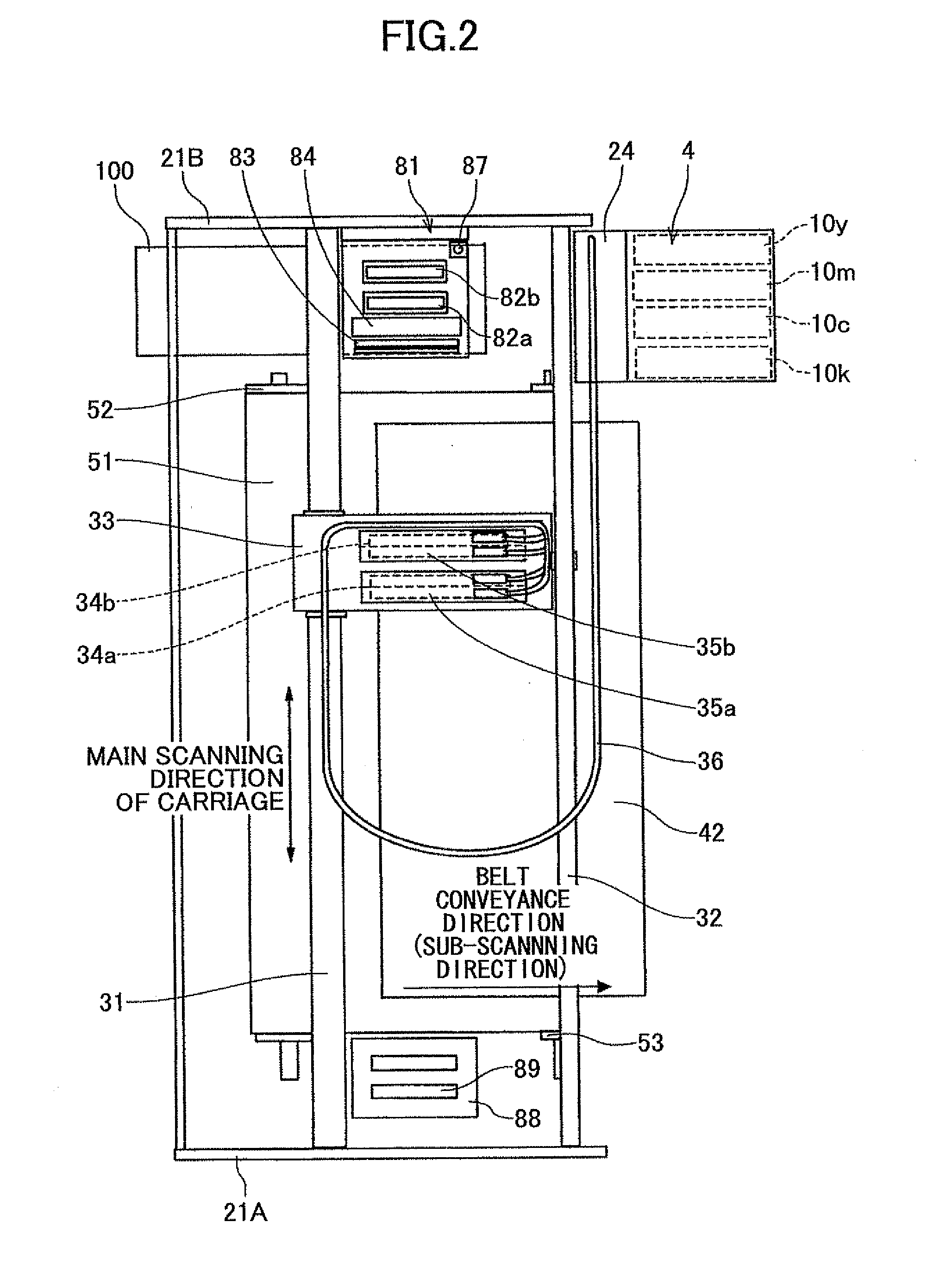
[0046]First, an example of an image forming apparatus having a liquid container of the present invention is discussed with reference to FIG. 1 and FIG. 2. Here, FIG. 1 is a schematic drawing showing the side view of an image forming apparatus according to one embodiment. FIG. 2 is a schematic drawing showing the plan view of a main portion of the image forming apparatus according to one embodiment.

[0047]The image forming apparatus of this embodiment is a serial type image forming apparatus and includes a main guide rod 31 and a sub-guide rod 32 which are supported at their lateral ends by side boards 21A, 21B. The main guide rod 31 and the sub-guide rod 32 slidably hold a carriage 33. The carriage 33 is moved to scan by a main scanning motor (not shown in FIG. 1 and FIG. 2) via a timing belt in the direction of an arrow (main scanning direction of the carriage) shown in FIG. 2.

[0048]The carriage 33 carries a liquid ejecting head including ejecting heads 34a and 34b which eject ink l...

second embodiment

[0086]Here, an elastically deformable sealing member 251 having a drum-shaped configuration is provided between the filter holding member 250 and the holder 222 forming the holding part so as to cover the external circumferential side of the opening member 241. An inside of the sealing member 251 is used as the air room 244b having a large volume and communicating with the air room 244. The action and the effect of this embodiment is the same as the

[0087]Next, a liquid container of a fourth embodiment of the present invention is discussed with reference to FIG. 11 and FIG. 12. FIG. 11 is an expanded cross-sectional view of an air opening mechanism of the liquid container of the fourth embodiment of the present invention. FIG. 12 is an exploded perspective view of the air opening mechanism of the liquid container of the fourth embodiment of the present invention. In FIG. 11 through FIG. 12, parts that are the same as the parts shown in FIG. 1 through FIG. 8 of the first embodiment of...

fourth embodiment

[0095]In this embodiment as well as the fourth embodiment, a packing as the seat member 223 is provided inside the holder 222 attached to the holder attaching part 221. The seat member 223 and a valve body part 262 form a valve part. The valve part and an opening member part 263 are formed in a body so that the valve member 261 is formed. The opening member part 263 is configured to open the valve part with the seat member 223 by being pressed from the outside. The valve member 261 is movably provided. The air communicating path 242 forming a part of the air opening path 220 is formed between the holder 222 and a groove 263a of the opening member part 263 of the valve member 261.

[0096]Here, the valve body part 262 of the valve member 261 is pressed to the seat member 223 by a force of the coil spring 225 so that air blocking is performed.

[0097]A filter member 243 having an external surface coming in contact with the atmosphere is held by the holder 222 as the holding part. An air ro...


PUM


Abstract

An image forming apparatus, includes a liquid jet head; a container main body; an air opening mechanism configured to open and close an air opening path in the container main body. The air opening mechanism includes a holding part, and an opening member movably provided at the holding part. The opening member includes an air communicating path, a filter member, and an air room. An opening cross-sectional area of the air room in a direction perpendicular to an air flow-in direction is greater than an opening cross-sectional area of the air communicating path in a direction perpendicular to an air flow-in direction.

Description

TECHNICAL FIELD[0001]The present invention generally relates to liquid containers and image forming apparatuses. More specifically, the present invention relates to an image forming apparatus having a recording head configured to jet liquid drops and a liquid container used in the image forming apparatus.BACKGROUND ART[0002]As an image forming apparatus such as a printer, facsimile, copier, plotter, or a multifunctional peripheral including the printer, facsimile, copier, and the plotter, an inkjet recording apparatus is known. The inkjet recording apparatus is a liquid jet recording type image forming apparatus using a recording head configured to jet ink liquid drops. In this liquid jet recording type image forming apparatus, the ink liquid drops are jetted from the recording head onto a conveyed sheet so that image forming such as recording or printing is performed.[0003]Hereinafter, the “image forming apparatus” means an apparatus configured to jet liquid onto a medium such as a...

Claims


Application Information

Patent Timeline
Patent Type & Authority Applications(United States)
IPC IPC(8): B41J2/175
CPCB41J2/175B41J2/17509B41J2/19B41J3/60B41J2/17513B41J2/17563
Inventor TSUKAMURA, KIYOSHIHIRATANI, KENJIKIKURA, MAKOTOOBATA, YUZONAKAMURA, DAISUKE
Owner RICOH KK
Why Eureka
Try Eureka