Image processing apparatus, image processing method, and computer program product

a technology of image processing which is applied in the field of image processing apparatus and image processing method, and computer program products, can solve the problems of weak representational power of output material through two-color printing, chromatic color and achromatic color might decrease,

Inactive Publication Date: 2011-06-16
RICOH KK
View PDF53 Cites 18 Cited by
  • Summary
  • Abstract
  • Description
  • Claims
  • Application Information

AI Technical Summary

Problems solved by technology

Thus, depending on the manner in which the color tone of black is deviated and on the combination of black and a chromatic color, the color contrast between the chromatic color and the achromatic color might decrease; which results in a problem in that the representational power of the output material through two-color printing becomes weak. FIG. 22 is a diagram illustrating an example of a difference in color between the achromatic color and the chromatic color in the case in which an ideal black coloring material is used; and an example of a difference in chromaticity between the achromatic color and the chromatic color in the case in which a black coloring material that has been used practically is used.

Method used


Image

  • Image processing apparatus, image processing method, and computer program product
  • Image processing apparatus, image processing method, and computer program product
  • Image processing apparatus, image processing method, and computer program product

Examples


first embodiment

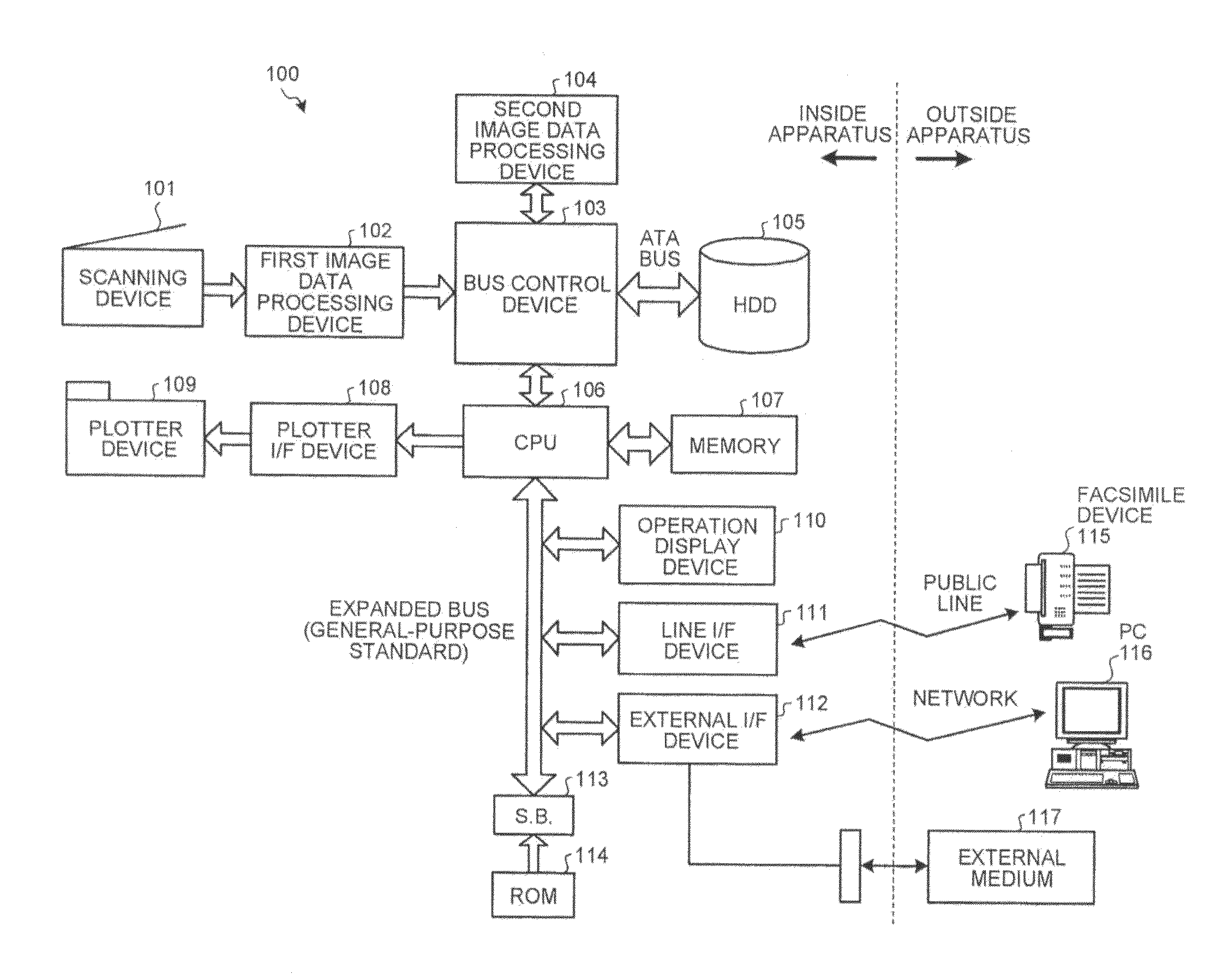
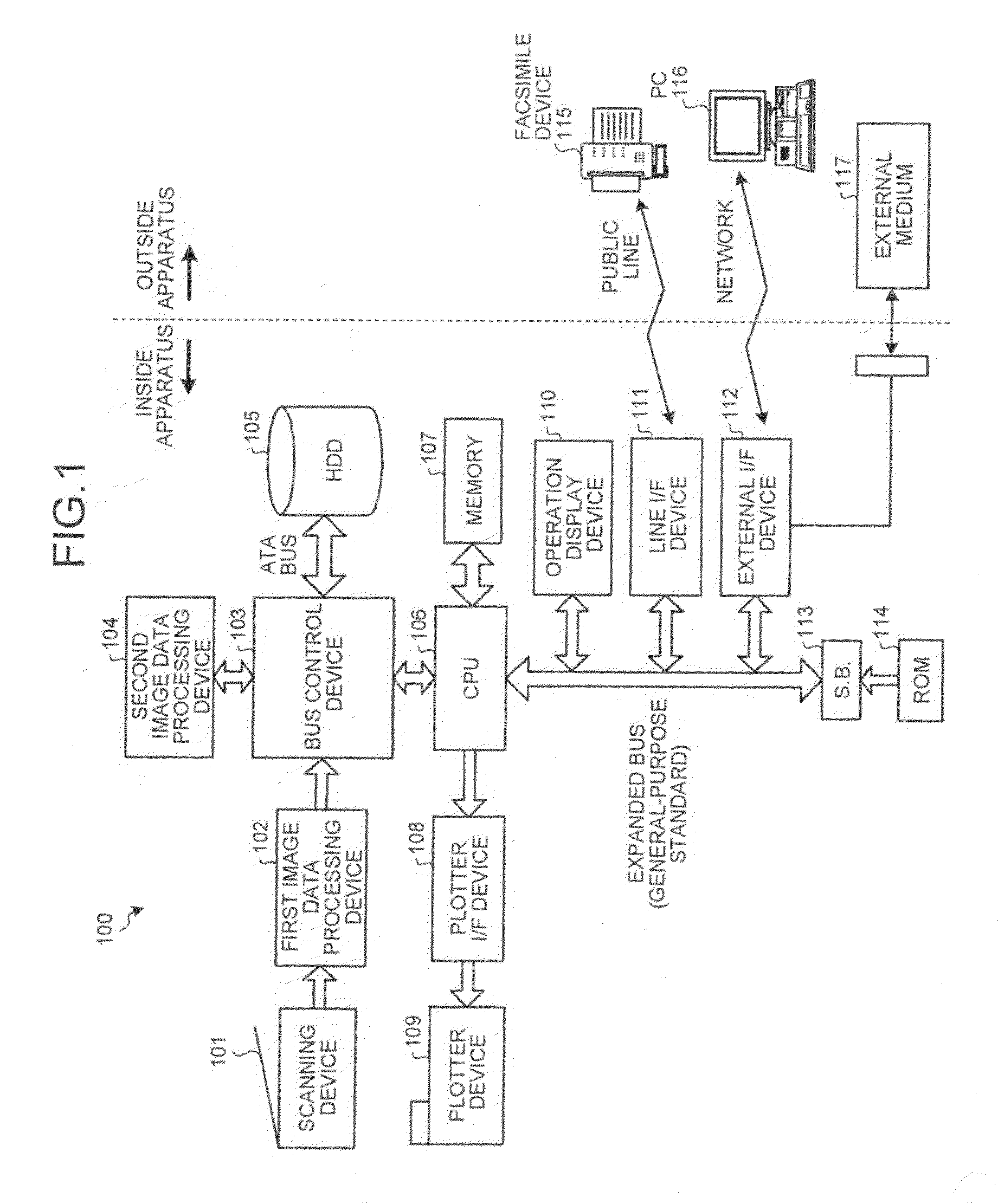
[0036]FIG. 1 is a block diagram showing the overall structure of an MFP according to a first embodiment. A scanning device 101 includes a line sensor that is configured by a photoelectric conversion element (for example, Charge Coupled Device (CCD)), an A / D converter, and driving circuits thereof. The scanning device 101 generates digital image data of RGB each having 0.8 bits based on shading information of a document that is acquired by scanning the document that is set and outputs the generated digital image data. In this embodiment, although the scanning device 101 includes the CCD, the same structure may be employed even in the case where an image sensor such as a Contact Image Sensor (CIS) or a CMOS is included. In addition, in accordance with a recent trend of an increase in the number of scanned bits, digital image data of RGB each having 10 bits or 12 bits may be generated.

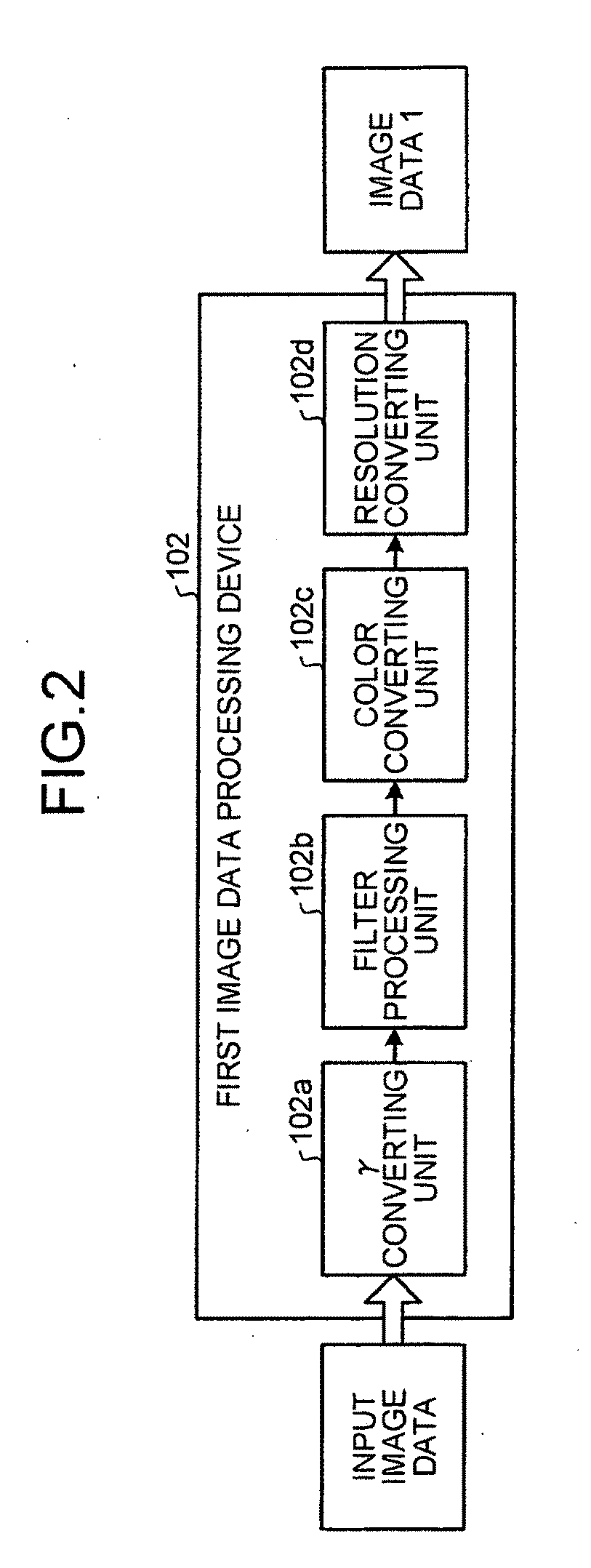
[0037]A first image data processing device 102 performs image processing of the digital image data out...

modified example 1

[0194]This modified example is an example in which the role of transforming the color space is transferred from the color converting unit to a three-dimensional lookup table (SDLUT), and the role of the color converting unit is clarified to be generation of output image data in which the chromatic color and the achromatic color included in the input image data are substituted with other colors. The description of the same portion as that of the first embodiment is omitted here.

[0195]FIG. 18 is a block diagram showing a detailed structure of a color converting unit. A color converting unit 1801, similarly to the first embodiment, defines colors included in the input image data and the output image data as vectors for each hue of the input image data.

[0196]However, the vector of the color included in the input image data and the vector of the color included in the output image data do not relate to an output destination (for example, printing or transferring) of the output image data;...

modified example 2

[0198]This modified example is an example in which the color tone of the achromatic color included in the output image data is adjusted in accordance with the degree of whiteness of a sheet. The description of the same portion as that of the first embodiment is omitted here.

[0199]FIG. 19 is a schematic diagram illustrating an example of enhancement in the color contrast according to the degree of whiteness of a sheet. FIGS. 20A to 20C are chromaticity diagrams of the output image data of which the color contrast is enhanced in accordance with the degree of whiteness of a sheet. In a two-color printing process or the like, in the case in which the degree of whiteness of a sheet is low, and the color tone of “black” included in the output image data is deviated in the direction of “red” (shown in FIG. 19), compared to a difference in the chromaticity between “black” and “red” included in the output image data in the case in which the degree of whiteness of a sheet is sufficient (FIG. ...


PUM


Abstract

An image processing apparatus includes: a setting unit that sets a color index representing a category to which an achromatic color and at least one chromatic color that are included in image data belong; an adjustment unit that adjusts a color tone of the achromatic color belonging to the category that is indicated by the set color index in accordance with a hue of the chromatic color belonging to the category; and a generation unit that generates image data including the chromatic color belonging to the category and the achromatic color of which the color tone is adjusted by the adjustment unit.

Description

CROSS-REFERENCE TO RELATED APPLICATIONS[0001]The present application claims priority to and incorporates by reference the entire contents of Japanese Patent Application No. 2009-285651 filed in Japan on Dec. 16, 2009 and Japanese Patent Application No. 2010-246728 filed in Japan on Nov. 2, 2010.BACKGROUND OF THE INVENTION[0002]1. Field of the Invention[0003]The present invention relates to an image processing apparatus, an image processing method, and a computer program product.[0004]2. Description of the Related Art[0005]Generally, in MFPs (Multi Function Peripherals) and printers, the printing cost of full-color output is higher than that of monochrome output. Accordingly, under some circumstances in which reduction of the printing cost is important, the use of the MFPs or printers may be supervised to be restricted to monochrome output by a supervisor of a system including the MFPs, the printers, and the like in many cases.[0006]Even when the use of the MFP or the printer is rest...

Claims


Application Information

Patent Timeline
Patent Type & Authority Applications(United States)
IPC IPC(8): H04N1/60
CPCH04N1/6002H04N1/56H04N1/6027
Inventor TOGAMI, ATSUSHI
Owner RICOH KK
Why Eureka
Try Eureka