Conduction cooled circuit board assembly

a technology of circuit board and cooling circuit board, which is applied in the direction of cooling/ventilation/heating modification, support structure mounting, lighting and heating apparatus, etc., can solve the problems of adversely affecting the performance of electronic devices, large temperature gradient between electronic devices, and insufficient dissipation of previous assemblies

Active Publication Date: 2011-06-16
GENERAL ELECTRIC CO
View PDF20 Cites 34 Cited by
  • Summary
  • Abstract
  • Description
  • Claims
  • Application Information

AI Technical Summary

Problems solved by technology

This leads to a larger temperature gradient between the electronic devices that are generating heat and the heat sink.
This larger temperature gradient may adversely affect the performance of the electronic devices.
Previous assemblies have not been adequate in dissipating the increased heat generated by higher power PCBs.

Method used


Image

  • Conduction cooled circuit board assembly
  • Conduction cooled circuit board assembly
  • Conduction cooled circuit board assembly

Examples


Embodiment Construction

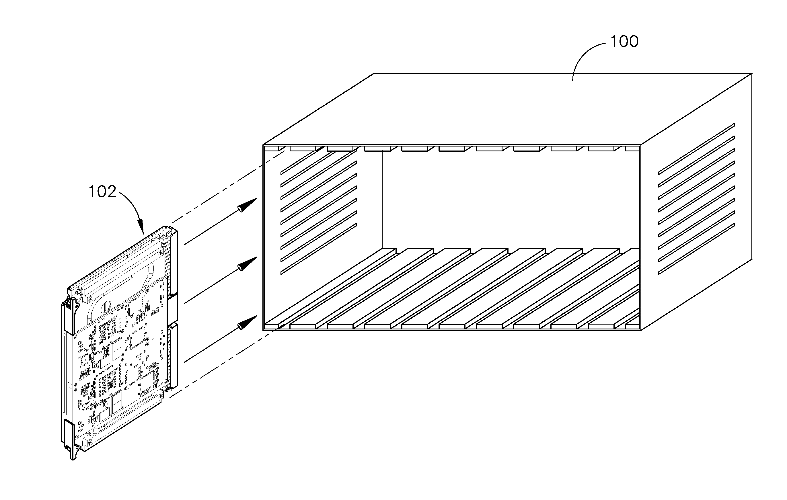
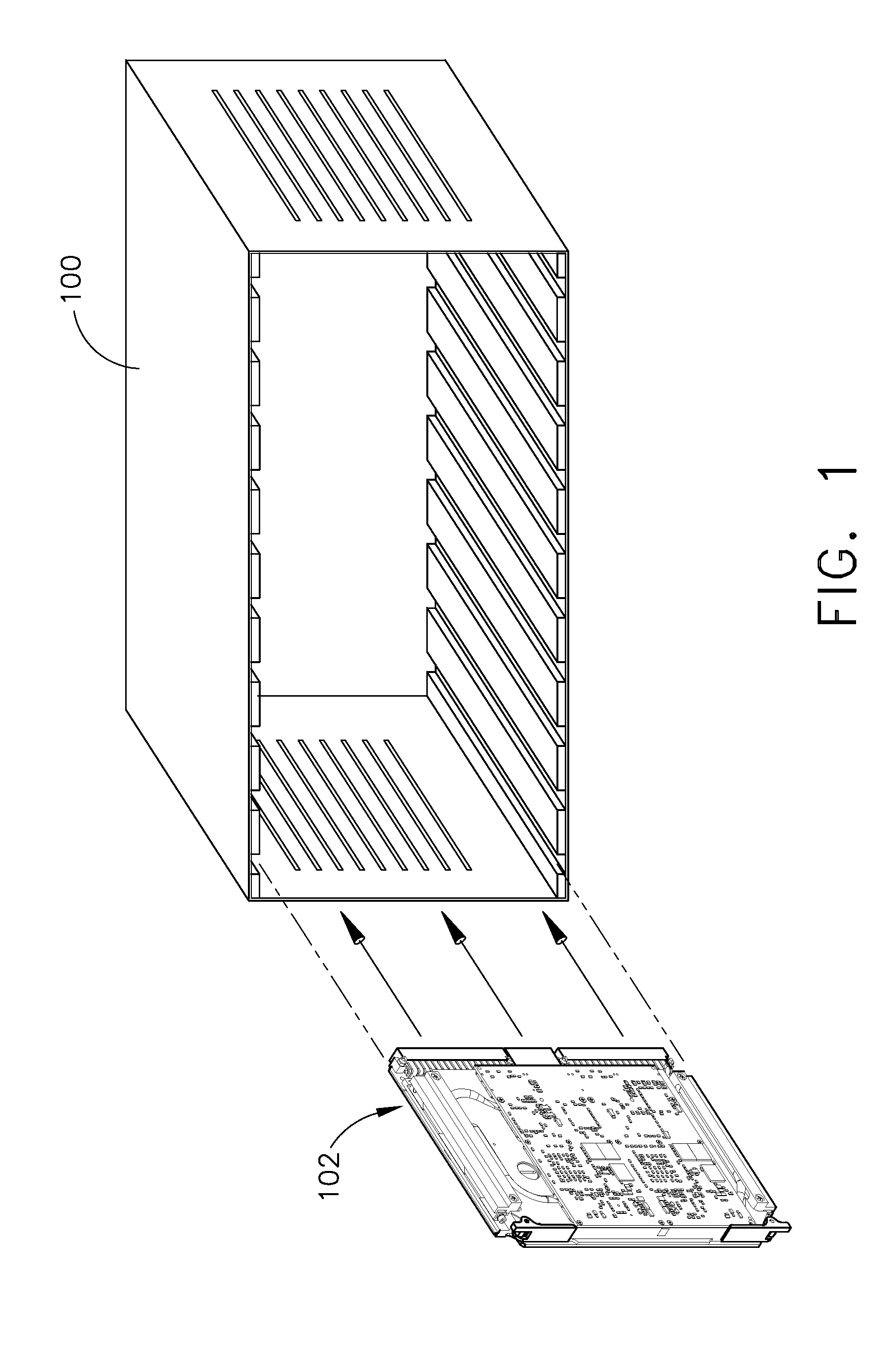
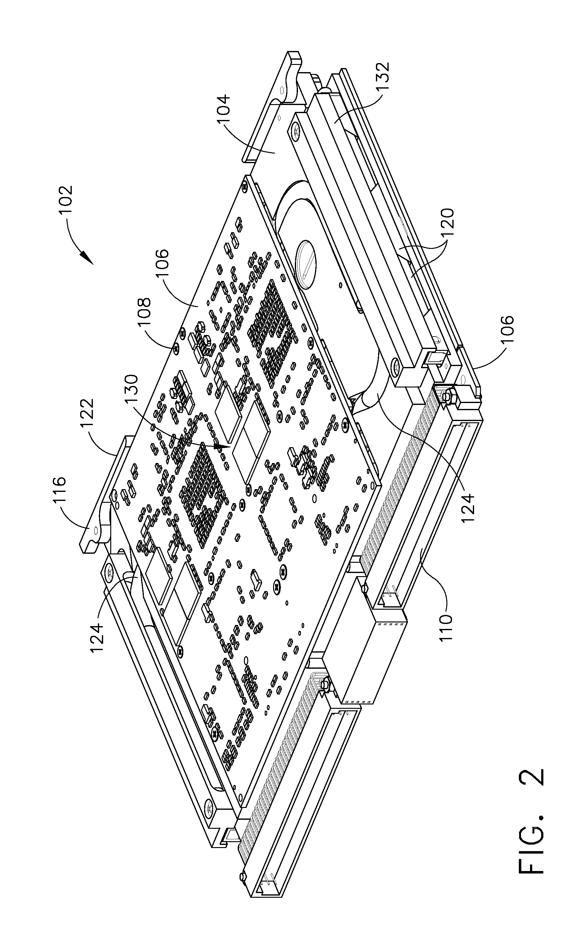
[0015]FIG. 1 is a perspective view of one exemplary embodiment of a chassis 100 having a circuit board assembly 102 associated therewith. The chassis 100 may be included as part of an avionics package for an aircraft (not shown) or other similar environment. The circuit board assembly is shown in more detail in FIGS. 2-5. FIG. 2 is a perspective view and FIG. 3 is a partially exploded perspective view of one exemplary embodiment of a circuit board assembly 102. The circuit board assembly 102 may have a frame 104. The frame 104 may be made of any material or combination of materials that may be thermally conductive, such as, but not limited to, aluminum, copper, composites or any combination thereof. The frame 104 may serve as the mechanical support for all other components of the circuit board assembly 102. One or more circuit boards 106 may be attached to the frame 104 in any manner known in the art, such as, but not limited to, mechanical fasteners 108, adhesives, etc. The circuit...


PUM


Abstract

A conduction cooled circuit board assembly may include a frame and at least one circuit board attached to the frame, having at least one area to be cooled. The assembly may also include at least one rail attached to the frame, and at least one heat pipe having a first end and a second end, the first end disposed near the area and the second end in contact with the rail so as to transfer heat from the area to the rail.

Description

BACKGROUND OF THE INVENTION[0001]The exemplary embodiments relate generally to electronic components and more specifically to a circuit board assembly having one or more heat pipes to enhance cooling of the circuit board.[0002]In avionics and other applications, printed circuit boards (“PCBs”) are commonly mounted within a chassis. The heat generated by electronic devices associated with the PCB may be dissipated by transfer to a metal wall of the chassis through the PCBs. The heat may then be sent to an external heat sink by conduction through the chassis wall, and is finally taken away by either cool air circulating about the heat sink or a cold plate. Because of high thermal resistance in the heat transfer path, the temperature generally increases with continued operation until steady state is reached. This leads to a larger temperature gradient between the electronic devices that are generating heat and the heat sink. This larger temperature gradient may adversely affect the per...

Claims


Application Information

Patent Timeline
Patent Type & Authority Applications(United States)
IPC IPC(8): H05K7/20
CPCH05K7/20672H05K7/1404
Inventor BULT, JEFF
Owner GENERAL ELECTRIC CO
Why Eureka
Try Eureka