Immersion-cooled and conduction-cooled method for electronic system

a technology of electronic system and conduction cooling, which is applied in the direction of electrical apparatus casing/cabinet/drawer, cooling/ventilation/heating modification, instruments, etc., can solve the problems of increasing the difficulty of cooling at the module and system level, and the approach becomes problemati

Active Publication Date: 2014-05-29
IBM CORP
View PDF2 Cites 22 Cited by
  • Summary
  • Abstract
  • Description
  • Claims
  • Application Information

AI Technical Summary

Problems solved by technology

This trend poses cooling challenges at the module and system levels.
However, this approach is becoming problematic, particularly in the context of a computer center installation (i.e., data center).

Method used


Image

  • Immersion-cooled and conduction-cooled method for electronic system
  • Immersion-cooled and conduction-cooled method for electronic system
  • Immersion-cooled and conduction-cooled method for electronic system

Examples


Embodiment Construction

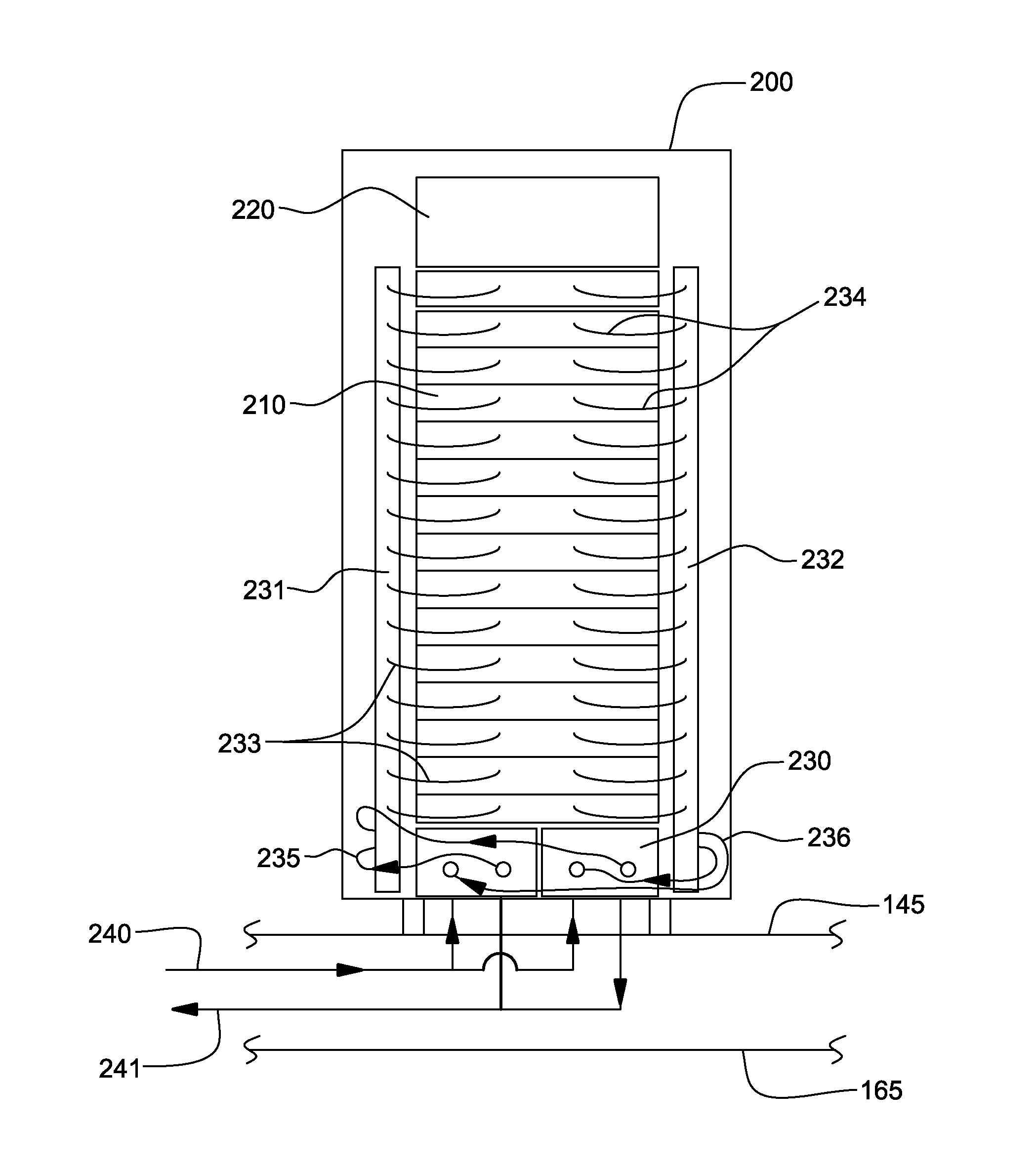
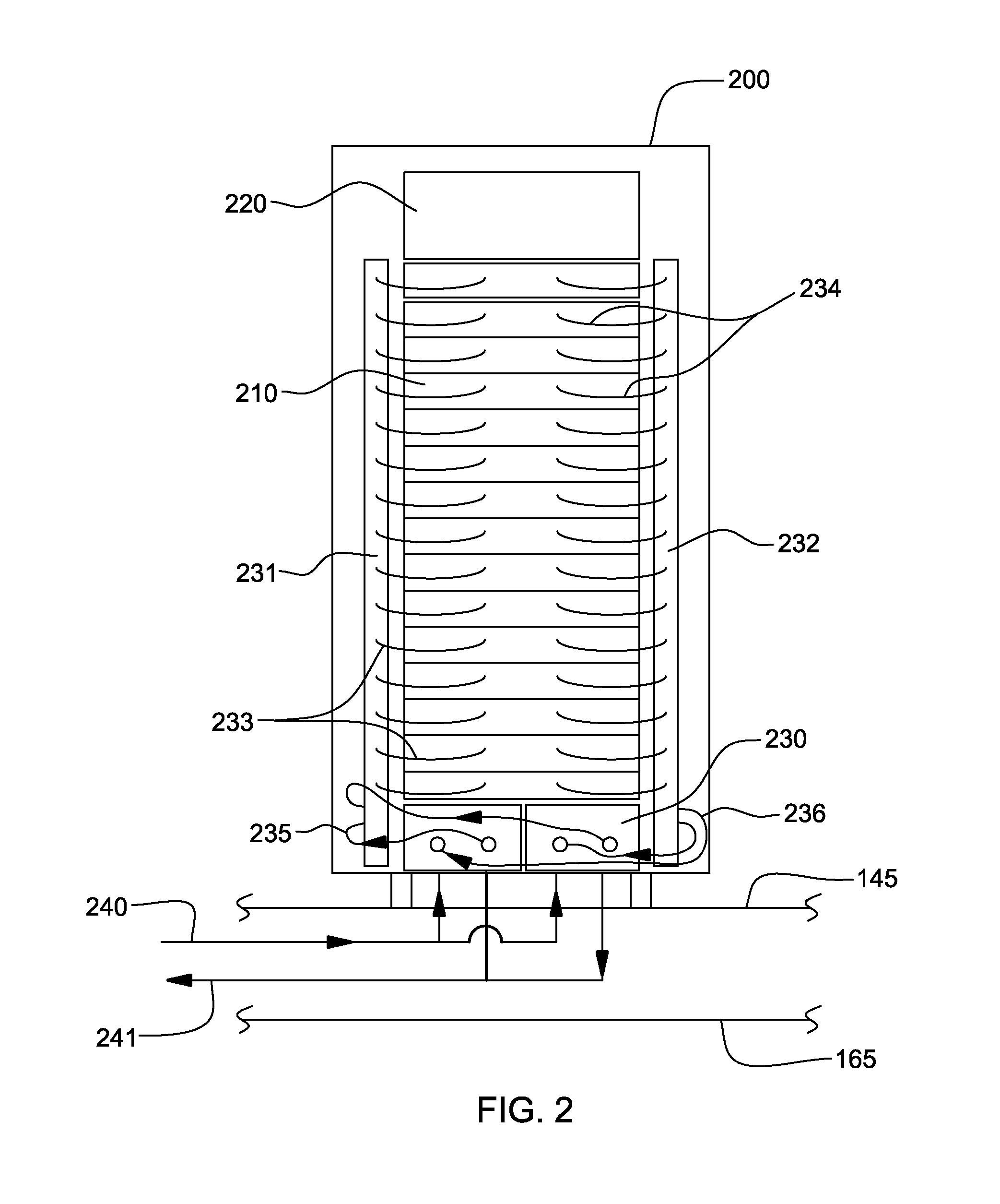
[0023]As used herein, the terms “electronics rack”, “rack-mounted electronic equipment”, and “rack unit” are used interchangeably, and unless otherwise specified include any housing, frame, rack, compartment, blade server system, etc., having one or more heat-generating components of a computer system, electronic system, or information technology equipment, and may be, for example, a stand alone computer processor having high-, mid- or low-end processing capability. In one embodiment, an electronics rack may comprise a portion of an electronic system, a single electronic system, or multiple electronic systems, for example, in one or more sub-housings, blades, books, drawers, nodes, compartments, etc., having one or more heat-generating electronic components disposed therein. An electronic system(s) within an electronics rack may be movable or fixed, relative to the electronics rack, with rack-mounted electronic drawers and blades of a blade center system being two examples of electr...


PUM


Abstract

A method of facilitating cooling of an electronics board having a plurality of electronic components mounted to the board by providing an apparatus which includes an immersion-cooled electronic component section and a conduction-cooled electronic component section. The immersion-cooled section includes an enclosure at least partially surrounding and forming a compartment about multiple electronic components of the electronic components mounted to the electronics board, and a fluid disposed within the compartment. The multiple electronic components are, at least in part, immersed within the fluid to facilitate immersion-cooling of those components. The conduction-cooled electronic component section includes at least one electronic component of the electronic components mounted to the electronics board, and the at least one electronic component is indirectly liquid-cooled, at least in part, via conduction of heat from the at least one electronic component.

Description

CROSS-REFERENCE TO RELATED APPLICATION[0001]This application is a continuation of U.S. Ser. No. 13 / 684,712, filed Nov. 26, 2012, and entitled “Immersion-Cooled and Conduction-Cooled Electronic System”, and which is hereby incorporated herein by reference in its entirety.BACKGROUND[0002]The power dissipation of integrated circuit chips, and the modules containing the chips, continues to increase in order to achieve increases in processor performance. This trend poses cooling challenges at the module and system levels.[0003]In many large server applications, processors along with their associated electronics (e.g., memory, disk drives, power supplies, etc.) are packaged in removable drawer configurations stacked within an electronics rack or frame comprising information technology (IT) equipment. In other cases, the electronics may be in fixed locations within the rack or frame. Typically, the components are cooled by air moving in parallel airflow paths, usually front-to-back, impell...

Claims


Application Information

Patent Timeline
Patent Type & Authority Applications(United States)
IPC IPC(8): H05K7/20
CPCH05K7/203H05K7/20236G06F1/20H05K7/20318H05K7/20336H05K7/2079H05K7/20809
Inventor CAMPBELL, LEVI A.CHU, RICHARD C.DAVID, MILNES P.ELLSWORTH, JR., MICHAEL J.IYENGAR, MADHUSUDAN K.SCHMIDT, ROGER R.SIMONS, ROBERT E.
Owner IBM CORP
Why Eureka
Try Eureka