Architectural lighting

a technology for architectural lighting and led light fixtures, applied in fixed installation, lighting and heating equipment, lighting support devices, etc., can solve the problems of difficult to meet the flexibility of a common fixture design, add to the difficulty of design and fabrication of architectural lighting fixtures, etc., and achieve the effect of convenient uniform placement and fabrication

Active Publication Date: 2011-06-16
ABL IP HLDG
View PDF21 Cites 80 Cited by
  • Summary
  • Abstract
  • Description
  • Claims
  • Application Information

AI Technical Summary

Benefits of technology

[0006]In a third separate aspect of the present invention, an LED light fixture includes a housing, a lens fixable on the housing and a flexible gasket. The housing has an elongate main body and two ends sealingly fixed to the main body. The main body has two parallel elongate channels extending the length thereof and each end has two channels which are aligned with the elongate channels and a cross channel between the end channels so as to form a seal channel rectangular in plan. The lens includes a seal ridge tapered to mate fully about the seal channel with the lens fixed in the housing. The gasket is positioned therebetween. This arrangement with the component housing allows for uniformity of product with different housing lengths. Again, architectural needs are readily accommodated.
[0007]In a fourth separate aspect of the present invention, the device of the third separate aspect further includes a mounting plate with light emitting diodes distributed on the mounting plate. A manifold plate is positioned on the mounting plate and includes holes therethrough with reflectors about the holes to receive the light emitting diodes. This facilitates uniform placement and fabrication, often with variations based solely on length.

Problems solved by technology

Such requirements often require flexibility that is difficult to satisfy with a common fixture design.
All such factors can add to difficulties in design and fabrication of architectural lighting fixtures.

Method used


Image

  • Architectural lighting
  • Architectural lighting
  • Architectural lighting

Examples


Embodiment Construction

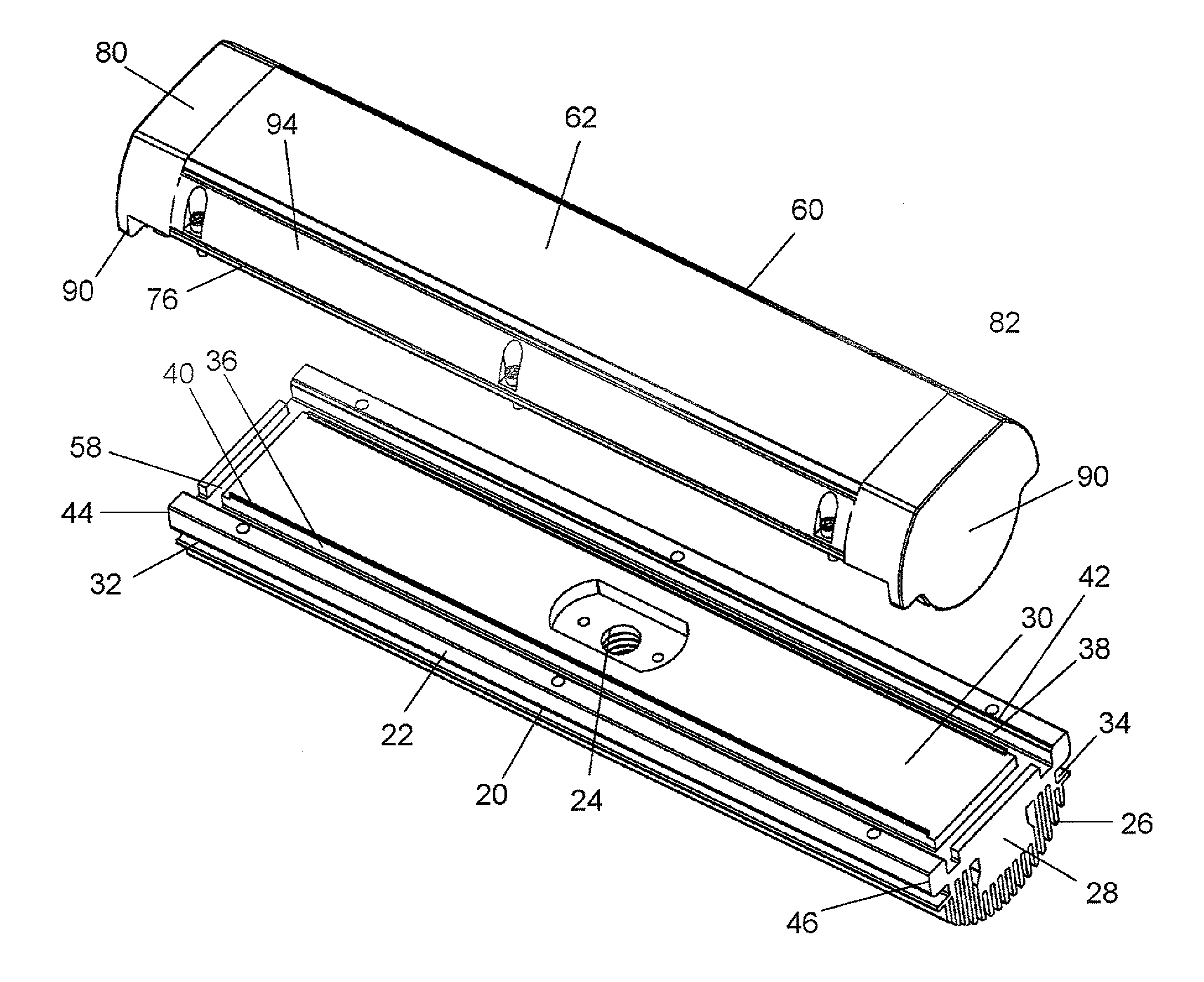
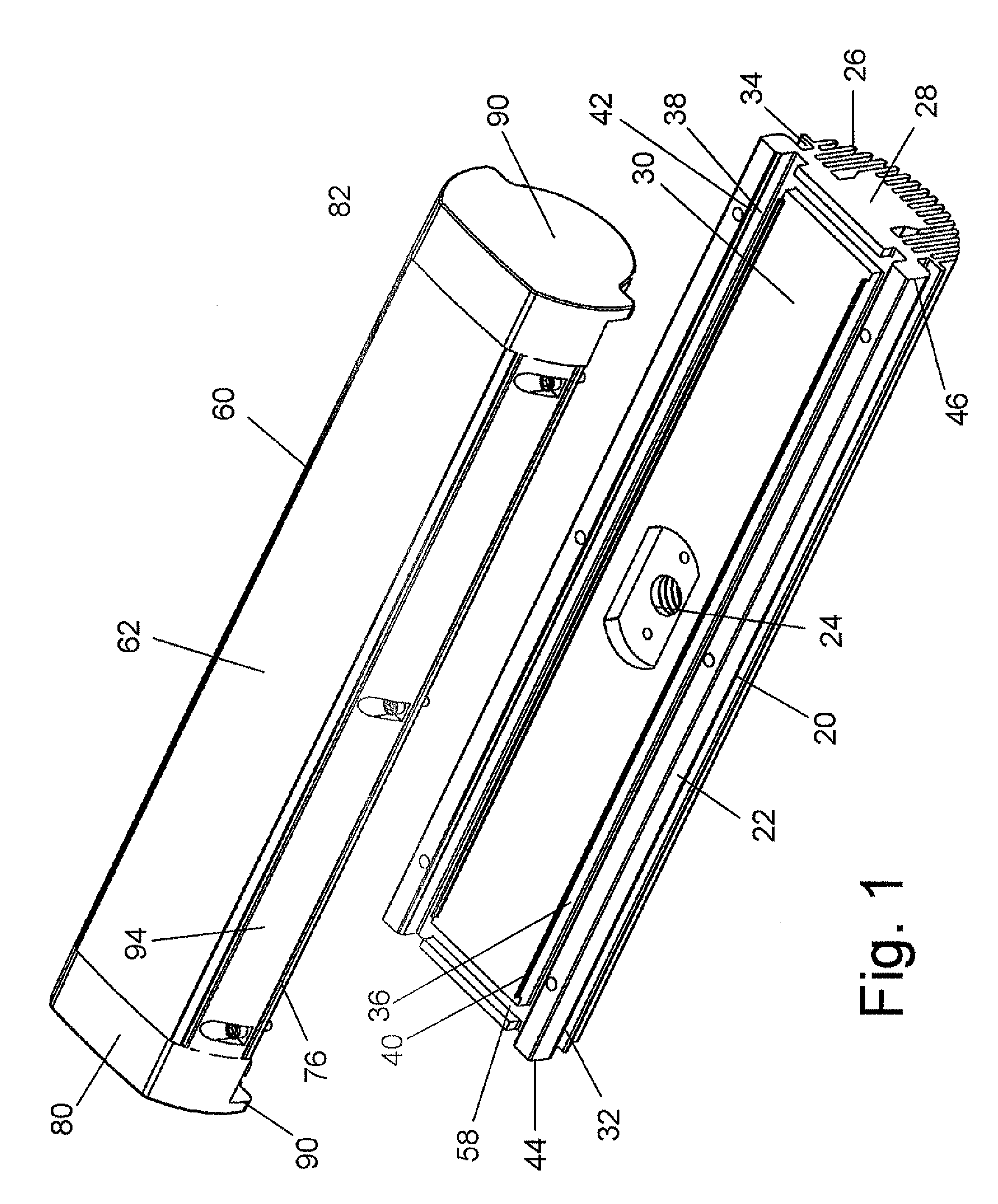
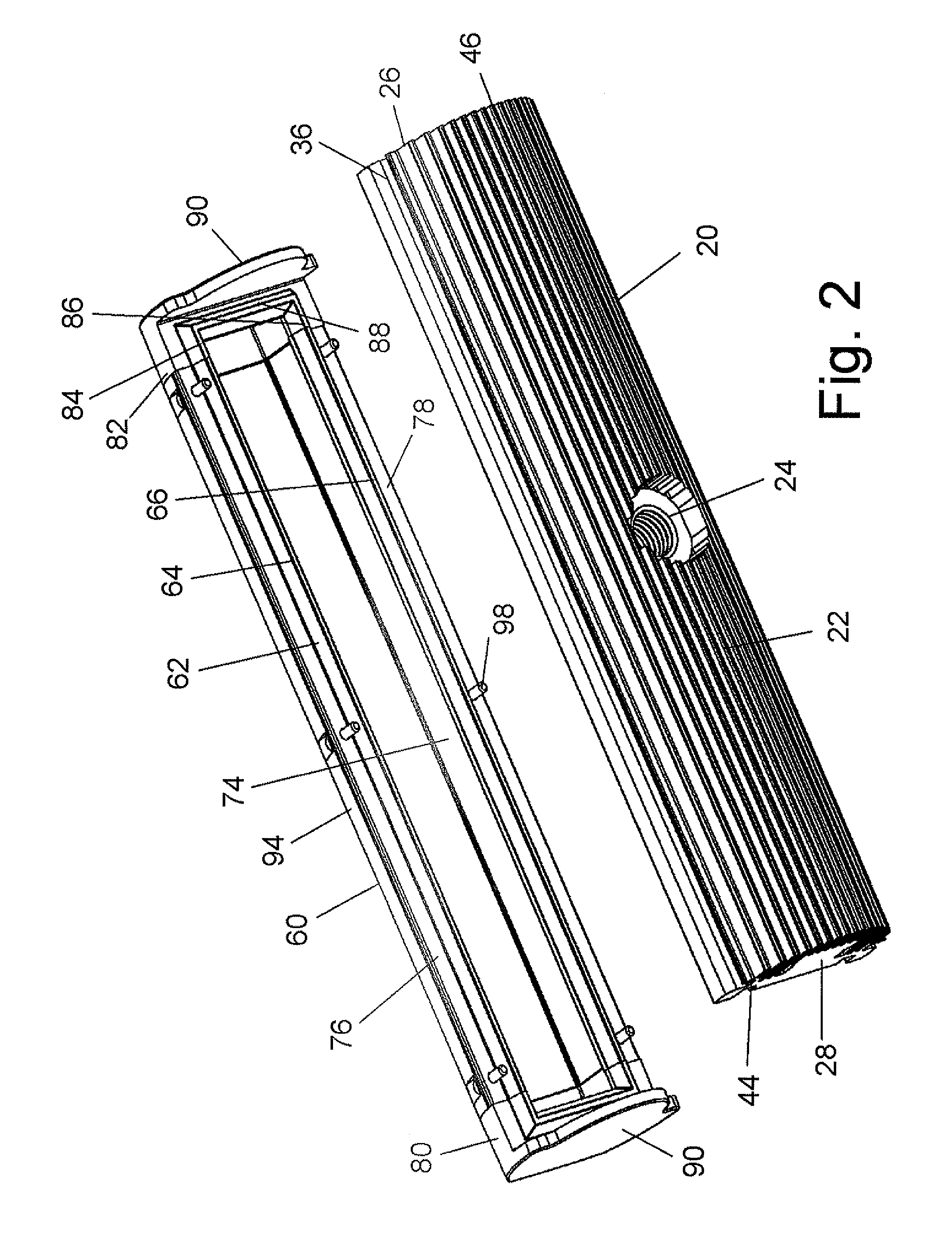
[0025]Turning in detail to the drawings, an LED light fixture has an elongate housing 20 with an extruded elongate main body 22. An access port 24 extends through the body 22 for electrical connections. The body 22 is thermally conductive with a substantial array of cooling fins 26 extending from an integral block 28 forming the base of the body 22. A mounting surface 30 to receive lighting elements is to one side of the base 28 opposite to the fins 26. Two opposed, outwardly facing channels 32, 34 extend the length of the elongate main body 22.

[0026]Two parallel elongate channels 36, 38 extend the length of the elongate main body 22 to either side of the mounting surface 30. These channels 36, 38 include outwardly beveled portions 40, 42 at the opening of each of the channels 36, 38. The beveled portions 40, associated with each of the channels 36, 38 inwardly on the main body 22 are formed by upstanding ridges defining the lateral extent of the mounting surface 30.

[0027]The elonga...


PUM


Abstract

An LED light fixture includes a housing, a lens and a flexible gasket there between. Each of the housing and the lens has an elongate main body and two ends sealingly fixed to the main body. The assembly of components in the housing defines a sealing channel rectangular in plan and the lens similarly defines a sealing ridge. A mounting plate with light emitting diodes distributed on the mounting plate further includes a manifold plate positioned on the mounting plate which includes holes therethrough with reflectors about the holes to receive the light emitting diodes. Mounts supporting the elongate housing define longitudinally adjustable engagements with the housing. The mounts further include tracks arranged in arcs of circles located in planes perpendicular to the extension of the elongate housing. Munting brackets engage these tracks using retainers.

Description

BACKGROUND OF THE INVENTION[0001]The field of the present invention is LED light fixtures for architectural lighting.[0002]Architectural lighting is typically employed to add dramatic effect to the architecture of a building or other structure. The nature, configuration and placement of the fixtures providing such lighting are responsive to the configuration and structure of the building. Consequently, versatile light fixtures are needed to accommodate wide ranging demands for architectural lighting. Light intensity, light distribution, source position, adjustability and fixture appearance all can be factors in architectural lighting designs. Such requirements often require flexibility that is difficult to satisfy with a common fixture design. Additional demands placed on architectural lighting and the use thereof include moisture resistance, maintenance needs and adjustability. All such factors can add to difficulties in design and fabrication of architectural lighting fixtures.SUM...

Claims


Application Information

Patent Timeline
Patent Type & Authority Applications(United States)
IPC IPC(8): F21V29/00F21V5/00
CPCF21S4/008F21V29/763F21V7/0083F21V15/01F21V15/013F21V17/12F21V21/112F21V21/26F21V21/30F21V23/005F21V29/004F21V31/005F21W2131/107F21Y2103/003F21Y2101/02F21S8/036F21V29/507F21V3/00F21S4/28F21Y2103/10F21Y2115/10F21V29/75
Inventor ACAMPORA, KEN J.QUEVY, KRISTEN
Owner ABL IP HLDG
Why Eureka
Try Eureka