X-ray tube for microsecond x-ray intensity switching

a microsecond x-ray and intensity switching technology, applied in the field of x-ray tubes, can solve the problems of preventing proper positioning and focusing of the electron beam on the x-ray target, difficult introduction of a wire mesh grid, and rapid change of electron beam curren

Active Publication Date: 2011-06-16
GENERAL ELECTRIC CO
View PDF30 Cites 33 Cited by
  • Summary
  • Abstract
  • Description
  • Claims
  • Application Information

AI Technical Summary

Problems solved by technology

Currently available X-ray tubes employed in CT systems fail to control the level of electron beam intensity to a desired temporal resolution.
Unfortunately, the energy and duty cycle of the electron beam makes the introduction of an intercepting wire mesh grid difficu

Method used


Image

  • X-ray tube for microsecond x-ray intensity switching
  • X-ray tube for microsecond x-ray intensity switching
  • X-ray tube for microsecond x-ray intensity switching

Examples


Embodiment Construction

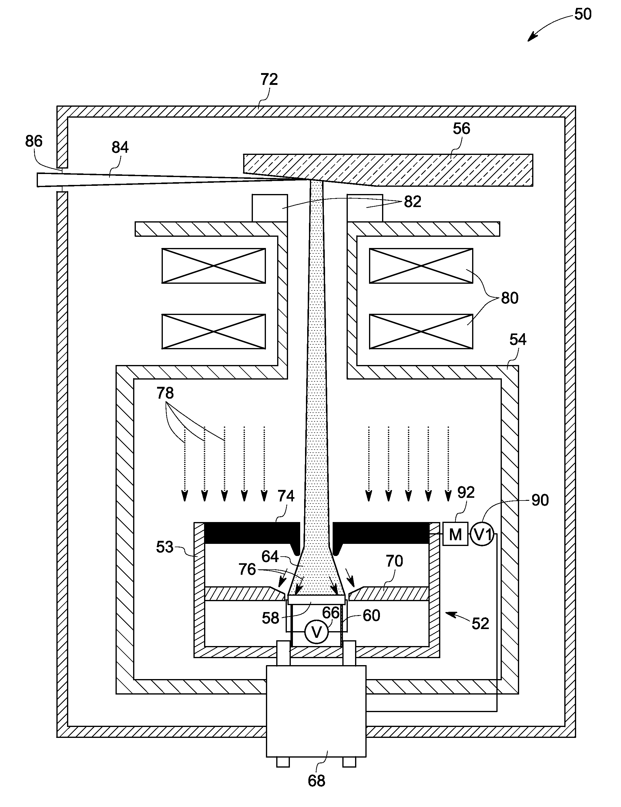
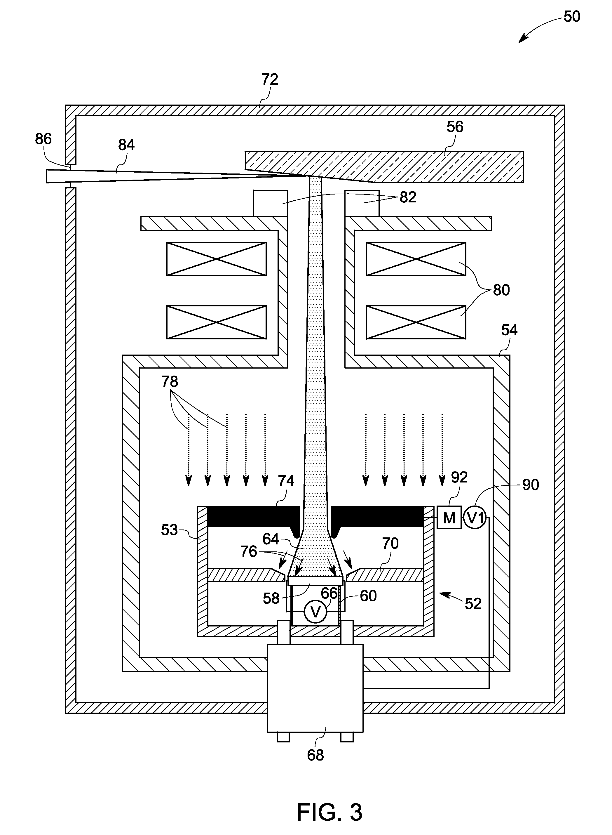
[0014]Embodiments of the present invention relate to microsecond X-ray intensity switching in an X-ray tube. An exemplary X-ray tube and a computed tomography system employing the exemplary X-ray tube are presented.

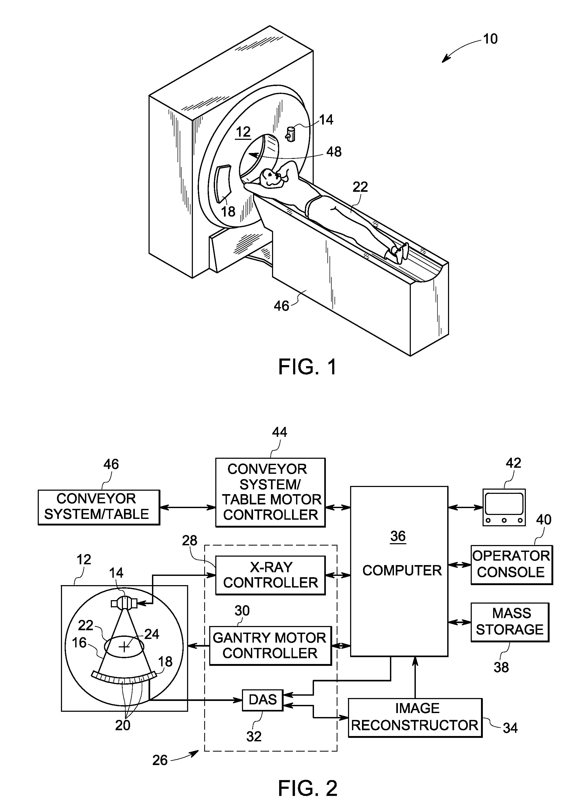
[0015]Referring now to FIGS. 1 and 2, a computed tomography (CT) imaging system 10 is illustrated. The CT imaging system 10 includes a gantry 12. The gantry 12 has an X-ray source 14, which typically is an X-ray tube that projects a beam of X-rays 16 towards a detector array 18 positioned opposite the X-ray tube on the gantry 12. In one embodiment, the gantry 12 may have multiple X-ray sources (along the patient theta or patient Z axis) that project beams of X-rays. The detector array 18 is formed by a plurality of detectors 20 which together sense the projected X-rays that pass through an object to be imaged, such as a patient 22. During a scan to acquire X-ray projection data, the gantry 12 and the components mounted thereon rotate about a center of rotation 24. While t...


PUM


Abstract

An injector for an X-ray tube is presented. The injector includes an emitter to emit an electron beam, at least one focusing electrode disposed around the emitter, wherein the at least one focusing electrode focuses the electron beam and at least one extraction electrode maintained at a positive bias voltage with respect to the emitter, wherein the at least one extraction electrode controls an intensity of the electron beam.

Description

BACKGROUND[0001]Embodiments of the present invention relate generally to X-ray tubes and more particularly to an apparatus for microsecond X-ray intensity switching.[0002]Typically, in computed tomography (CT) imaging systems, an X-ray source emits a fan-shaped beam or a cone-shaped beam towards a subject or an object, such as a patient or a piece of luggage. Hereinafter, the terms “subject” and “object” may be used to include anything that is capable of being imaged. The beam, after being attenuated by the subject, impinges upon an array of radiation detectors. The intensity of the attenuated beam radiation received at the detector array is typically dependent upon the attenuation of the X-ray beam by the subject. Each detector element of a detector array produces a separate electrical signal indicative of the attenuated beam received by each detector element. The electrical signals are transmitted to a data processing system for analysis. The data processing system processes the e...

Claims


Application Information

Patent Timeline
IPC IPC(8): H05G1/60H01J35/14H01J35/30
CPCH01J35/14H01J35/045H01J35/147H01J35/153
Inventor FRONTERA, MARK ALANZOU, YUNZAVODSZKY, PETER ANDRASLEMAITRE, SERGIOROGERS, CAREY SHAWN
Owner GENERAL ELECTRIC CO
Why Eureka
Try Eureka