Reproducing apparatus for video data

a technology for video data and equipment, applied in the field of reproducing equipment, can solve the problems of troublesome operation described above, and achieve the effect of easy converting a moving image forma

Active Publication Date: 2011-06-16
CANON KK
View PDF3 Cites 93 Cited by
  • Summary
  • Abstract
  • Description
  • Claims
  • Application Information

AI Technical Summary

Benefits of technology

[0007]It is an aspect of the invention to solve the problem described above, and provide an apparatus capable of easily converting a format of a moving image according to a storage destination.

Problems solved by technology

The operation described above is very troublesome.

Method used


Image

  • Reproducing apparatus for video data
  • Reproducing apparatus for video data
  • Reproducing apparatus for video data

Examples


first embodiment

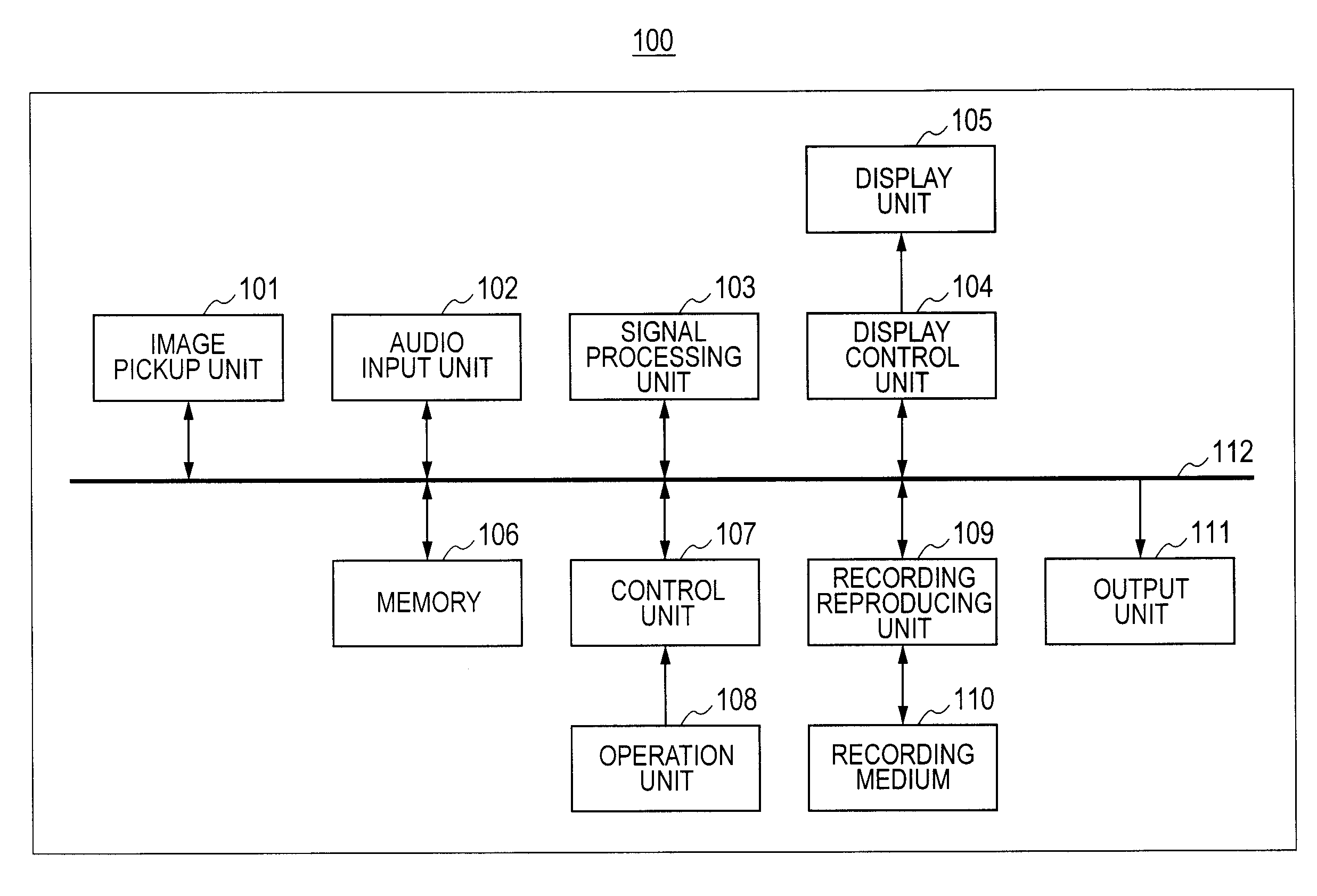
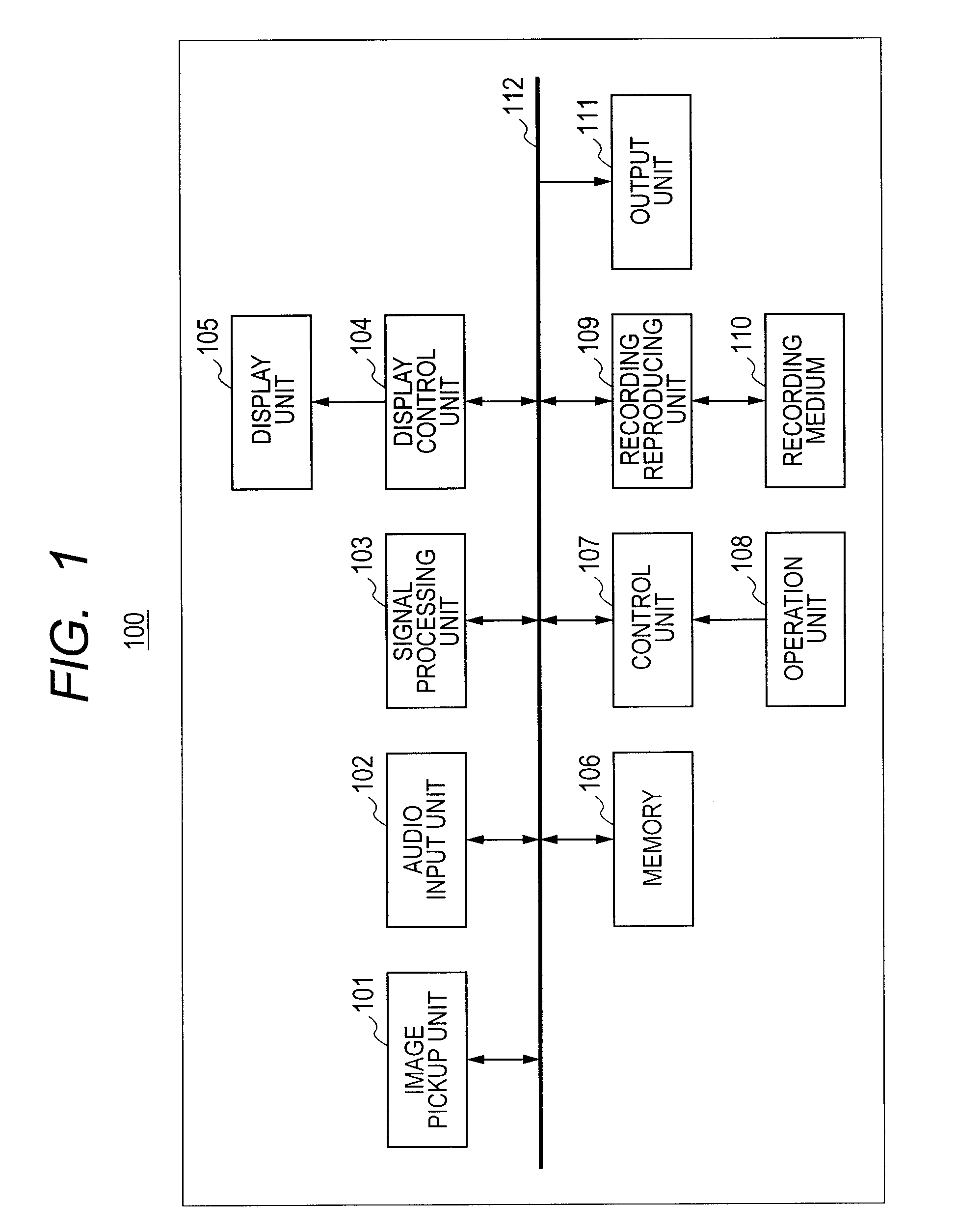
[0031]FIG. 1 is a block diagram illustrating a schematic configuration of a video camera 100 according to one embodiment of the present invention.

[0032]In FIG. 1, an image pickup unit 101 photographs an object, generates a moving image signal representing the object, and outputs the resultant. The image pickup unit 101 includes an optical system such as a zoom lens or a focusing lens, an image pickup element such as a CCD, an AD converter that converts the output image signal from the image pickup element into a digital signal, and processing circuit that performs necessary processes to the photographed moving image, for example. In the present embodiment, the image pickup unit 101 generates a high definition (HD method) moving image signal of 60 frames / second, each frame including 1920 pixels in wide and 1020 pixels in height. An audio input unit 102 picks up ambient sound of the video camera 100, and outputs an audio signal. The audio input unit 102 includes a microphone, an ampli...

second embodiment

[0108]A second embodiment will next be described. In this embodiment too, the configuration and the basic process of the video camera 100 are the same as those in the first embodiment. In the present embodiment, the conversion process can be instructed in a reproduction temporary stop state. FIG. 12 is a view illustrating the conversion process in the present embodiment.

[0109]As illustrated in FIG. 12, when the converting instruction is issued with the index screen being displayed, the conversion process is executed as stated in the first embodiment. When a user operates the operation unit 108 to temporarily stop the reproduction during the reproduction of the moving image in the first mode or the second mode, and then, the user issues the converting instruction, the conversion process is executed. For example, when the DVD is selected as the storage destination, the moving image and the audio from the position where the reproduction is temporarily stopped, to the end of the scene a...


PUM


Abstract

A reproducing apparatus arranged to reproduce a moving image signal of a scene from a recording medium, set one of a first reproduction mode for reproducing one scene selected from the moving image signal of a selected one scene and a second reproduction mode for reproducing the moving image signals according to a playlist, convert the moving image signal recorded on the recording medium into a format designated by a transmission destination of the moving image signal, and effect control in response to a conversion instruction such that, in the first reproduction mode, the moving image signal of the one scene is divided on a unit basis of predetermined time related to an upper limit time designated by the transmission destination of the moving image signal and in the second reproduction mode, the moving image signals of the plurality of scenes are combined and the combined moving image signal is divided on the predetermined time basis.

Description

BACKGROUND OF THE INVENTION[0001]1. Field of the Invention[0002]The present invention relates to a reproducing apparatus, and more particularly to a reproducing apparatus for video data.[0003]2. Description of the Related Art[0004]There has conventionally been known a video camera that photographs an object and records a moving image and audio of the object (for example, see Japanese Patent Application Laid-Open No. 2009-076175). In recent years, a moving image posting and browsing service on the Internet has been known, and a video camera having a function of uploading a moving image on a server having the service described above has been known. A user accesses to a specific home page or a site with the use of a personal computer or a portable terminal having a video reproducing function, thereby being capable of browsing the uploaded moving image. It is to be noted that there is, in general, a limitation on a length or a size of an uploadable moving image or a file format dependin...

Claims


Application Information

Patent Timeline
Patent Type & Authority Applications(United States)
IPC IPC(8): H04N5/77H04N5/93
CPCG11B27/034G11B27/105G11B27/326G11B27/329G11B27/34G11B2220/2562H04N21/4825H04N9/7921H04N21/2743H04N21/4223H04N21/42646H04N21/4325H04N21/440218H04N5/77
Inventor ISHII, AKIYOSHI
Owner CANON KK
Why Eureka
Try Eureka