
Lightning protection for wind turbines

a technology for wind turbines and protection from light, applied in wind turbines, wind motors with parallel air flow, discharge by conduction/dissipation, etc., can solve problems such as increasing problems, wind turbine damage, and potential loss of multiple large production units

Active Publication Date: 2011-06-16
GENERAL ELECTRIC CO
View PDF13 Cites 19 Cited by
  • Summary
  • Abstract
  • Description
  • Claims
  • Application Information

AI Technical Summary

Benefits of technology

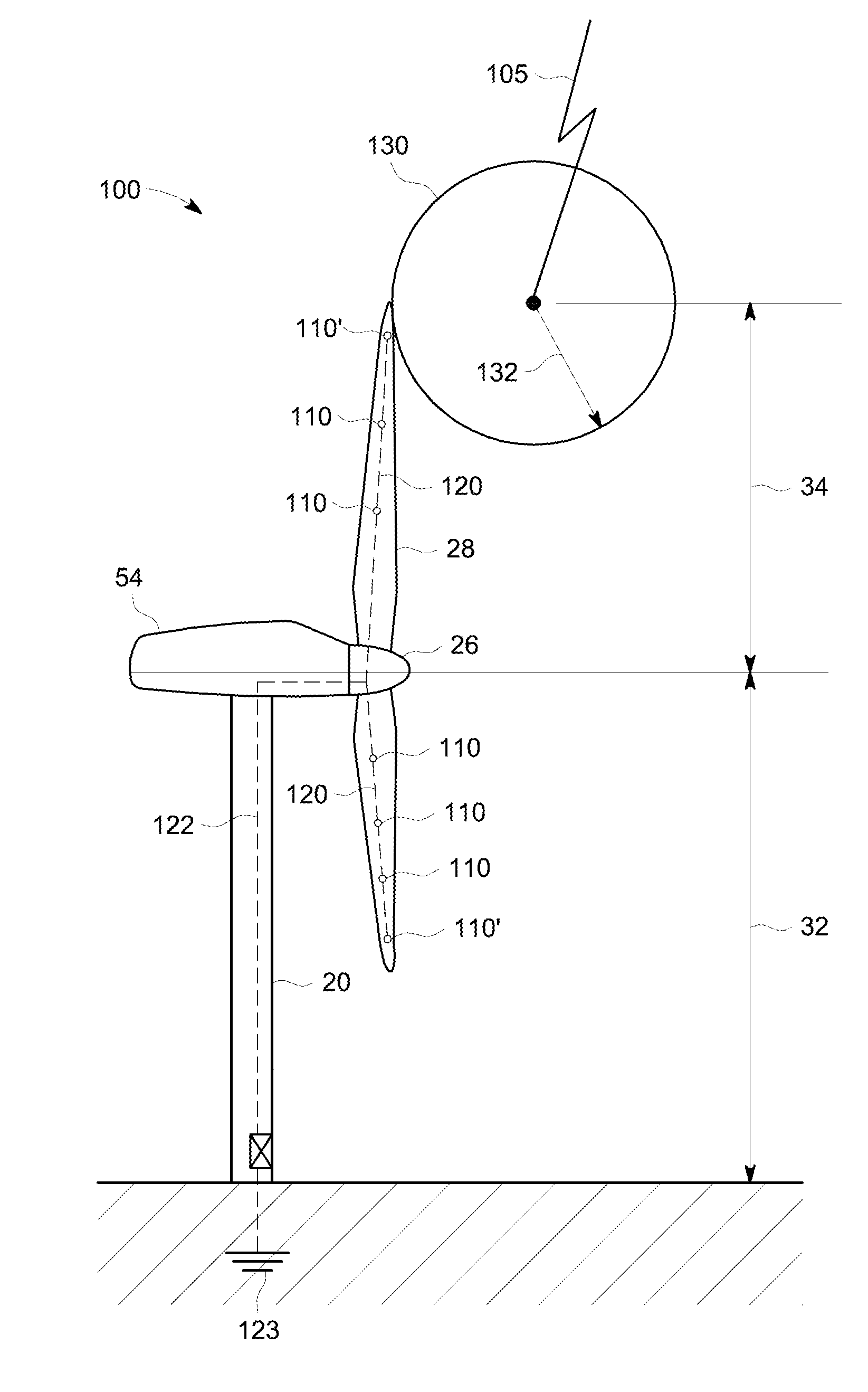
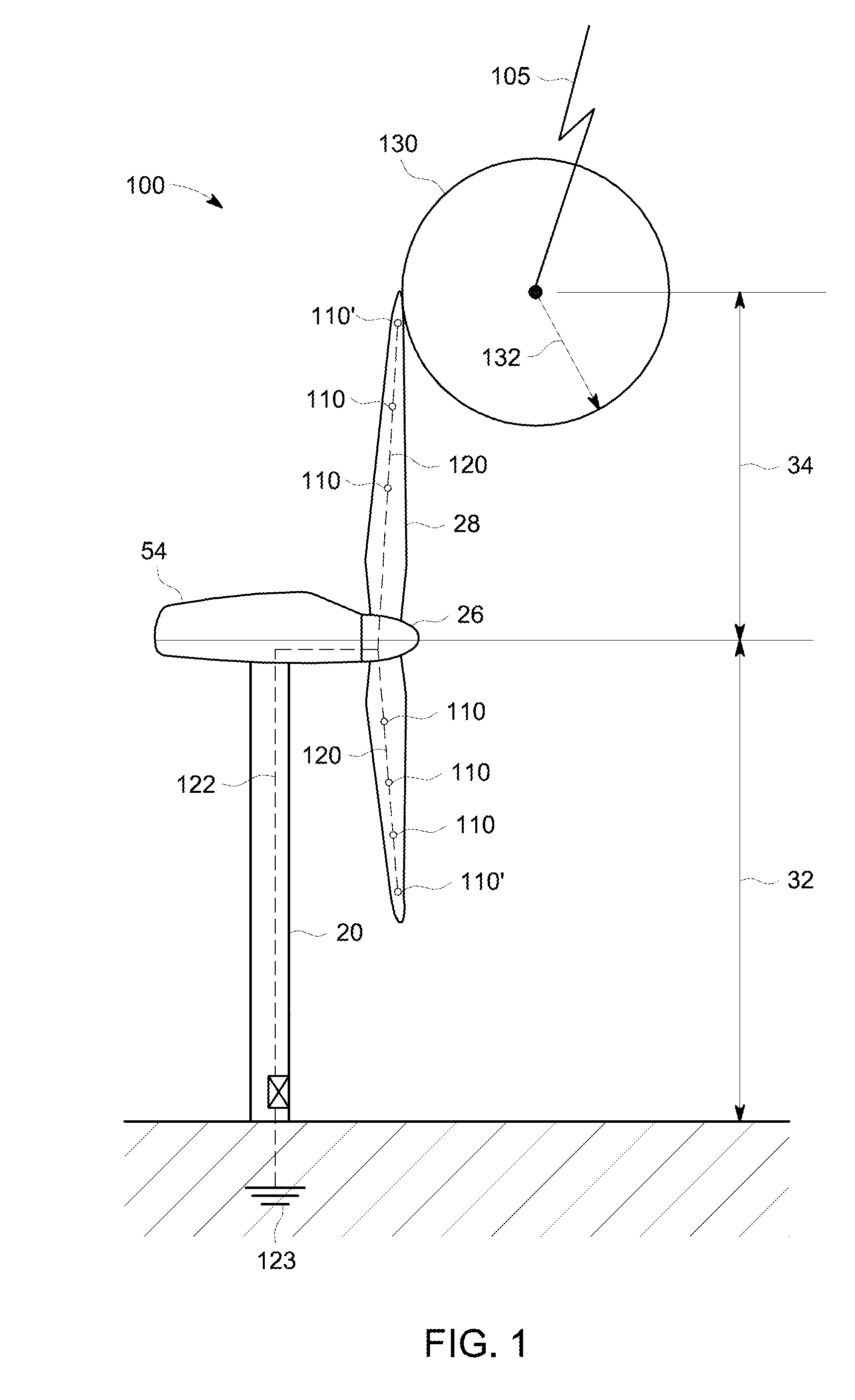
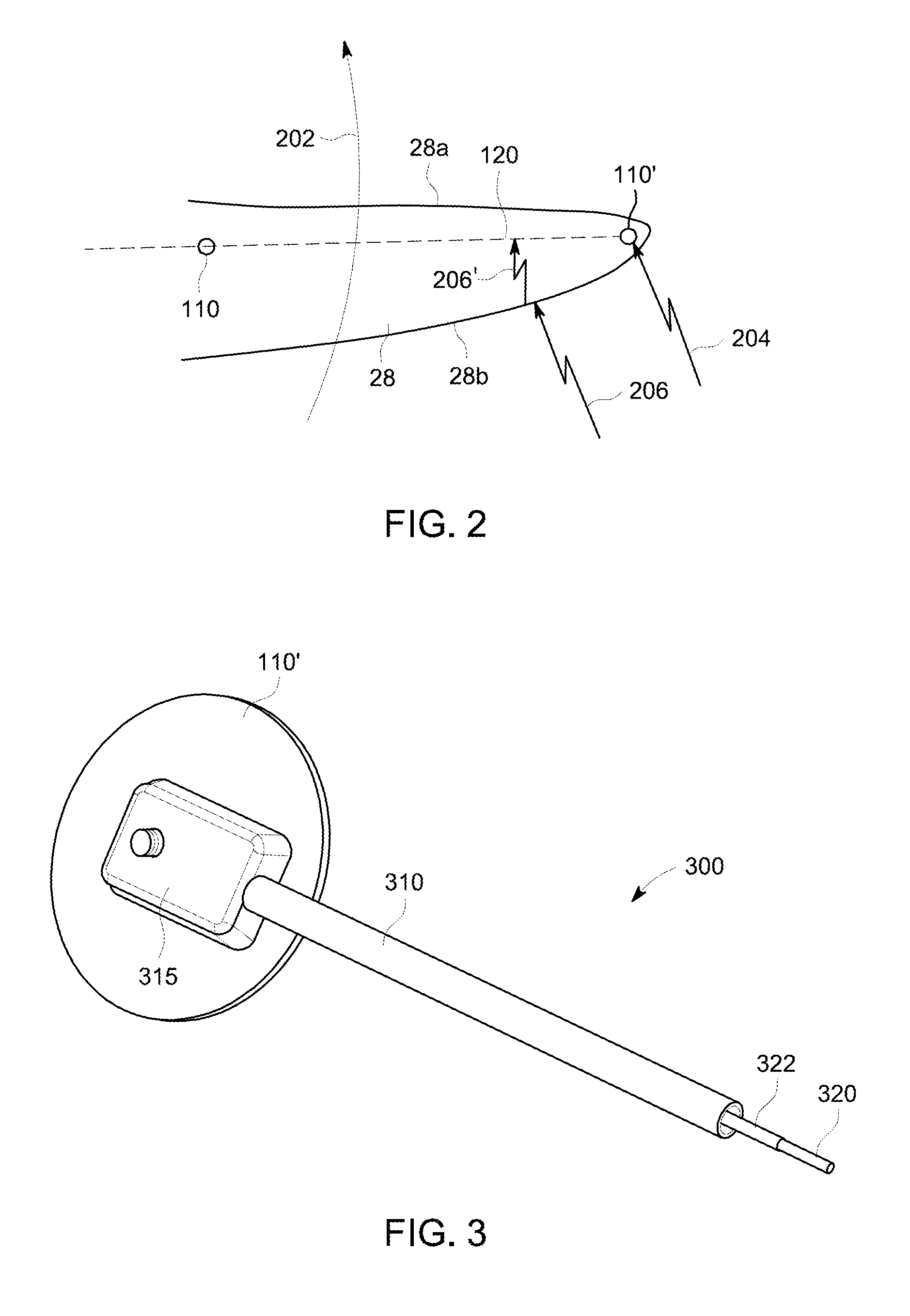
In view of the above, according to one aspect of the present invention, a rotor blade for a wind turbine is provided. The rotor blade includes a rotor blade body, at least one receptor adapted to be a location for lightning impact, and at least one down conductor connected to the receptor and located within the rotor blade body. The down conductor includes a first conductor connected to the receptor and a ground connection of the wind turbine, and a second insulated conductor connected to the receptor and a non-grounded location of the wind turbine. A path is formed from the ground connection of the first conductor to the non-grounded location of the second insulated conductor. This path facilitates a continuity test used to evaluate a condition of the lightning protection system.
According to another aspect of the present invention, a lightning protection system for a wind turbine is provided. The wind turbine includes a nacelle, a hub and one or more rotor blades. Each rotor blade includes a rotor blade body, at least one receptor adapted to be a location for lightning impact, and at least one down conductor connected to the receptor and located within the rotor blade body. The down conductor includes a first conductor connected to the receptor and a ground connection of the wind turbine, and a second insulated conductor connected to the receptor and a non-grounded location of the wind turbine. A path is formed from the ground connection of the first conductor to the non-grounded location of the second insulated conductor. This path facilitates a continuity test used to evaluate a condition of the lightning protection system.
According to yet another aspect of the present invention, a wind turbine is provided having a lightning protection system and one or more rotor blades. The wind turbine includes at least one rotor blade body and at least one receptor in the at least one rotor blade body, where the at least one receptor is adapted to be a location for lightning impact. At least one down conductor is connected to the at least one receptor, and located in the at least one rotor blade body. The down conductor includes a first conductor connected to the at least one receptor and a ground connection of the wind turbine, and a second insulated conductor connected to the at least one receptor and a non-grounded location of the wind turbine. A path is formed from the ground connection of the first conductor to the non-grounded location of the second insulated conductor. This path facilitates a continuity test used to evaluate a condition of the lightning protection system.

Problems solved by technology

Damage to wind turbines due to lightning strikes has been recognized as an increasing problem.
This is particularly the case when several large wind turbines are operated together in wind farm installations because the potential loss of multiple large production units due to one lightning strike may be significant.
Unlike other electrical installations such as overhead lines and power plants, it is more difficult for wind turbines to provide protective conductors that can be arranged around or above the wind turbine.
This is due to the physical size and nature of wind turbines.
However the internal connections of the down conductor may be damaged and are not easily found unless they are checked for continuity by comparing the ohm response between the receptor(s) and the tower or ground.
To access the blade tip receptor it requires a crane or expensive man basket apparatus.
This testing process is labor intensive, difficult and costly, and can only be performed as the weather permits.

Method used


Image

  • Lightning protection for wind turbines
  • Lightning protection for wind turbines
  • Lightning protection for wind turbines

Examples


Embodiment Construction

Reference will now be made in detail to the various aspects of the invention, one or more examples of which are illustrated in the figures. Each example is provided by way of explanation of the invention and is not meant as a limitation of the invention. For example, features illustrated or described as part of one aspect can be used on or in conjunction with other aspects to yield yet a further aspect. It is intended that the present invention includes such modifications and variations.

Modern wind turbine blades are structures manufactured of various materials, such as glass reinforced plastic (GRP), wood, wood laminate and carbon reinforced plastic (CRP). Parts and components such as mounting flanges, weights, bearings, wires, and electrical wiring are made of metal. Particularly, for blades constructed entirely from non-conducting materials, lightning attachment points, that is receptors, are mostly found close to the tip or distributed over the blade.

The generic problem of light...


PUM


Abstract

A rotor blade for a wind turbine is provided. The rotor blade includes a rotor blade body, at least one receptor adapted to be a location for lightning impact, and at least one down conductor connected to the receptor and located within the rotor blade body. The down conductor includes a first conductor connected to the receptor and a ground connection of the wind turbine, and a second insulated conductor connected to the receptor and a non-grounded location of the wind turbine. A path is formed from the ground connection of the first conductor to the non-grounded location of the second insulated conductor. This path facilitates a continuity test used to evaluate a condition of the lightning protection system.

Description

BACKGROUND OF THE INVENTIONThe present invention relates to lightning protection for wind turbines. More particularly, the invention relates to lightning protection for wind turbines and lightning protecting for rotor blades of wind turbines. Specifically, the invention relates to a rotor blade, a lightning protection system, and a method of manufacturing a rotor blade.Damage to wind turbines due to lightning strikes has been recognized as an increasing problem. The influence of lightning faults on the reliability of wind turbines and wind farms may become a concern as the capacity of wind turbines increases. This is particularly the case when several large wind turbines are operated together in wind farm installations because the potential loss of multiple large production units due to one lightning strike may be significant. Unlike other electrical installations such as overhead lines and power plants, it is more difficult for wind turbines to provide protective conductors that ca...

Claims


Application Information

Patent Timeline
IPC IPC(8): F03D11/00
CPCF03D1/00F03D11/0033F05B2260/80F05B2260/83H02G13/60H02G13/00Y02E10/722H02G13/80G01R31/2827F03D80/30Y02E10/72
Inventor HARDISON, RICHARD ALLENOLSON, STEVEN HAINES
Owner GENERAL ELECTRIC CO
Learn More