
System and method for determining and controlling gain margin in an RF repeater

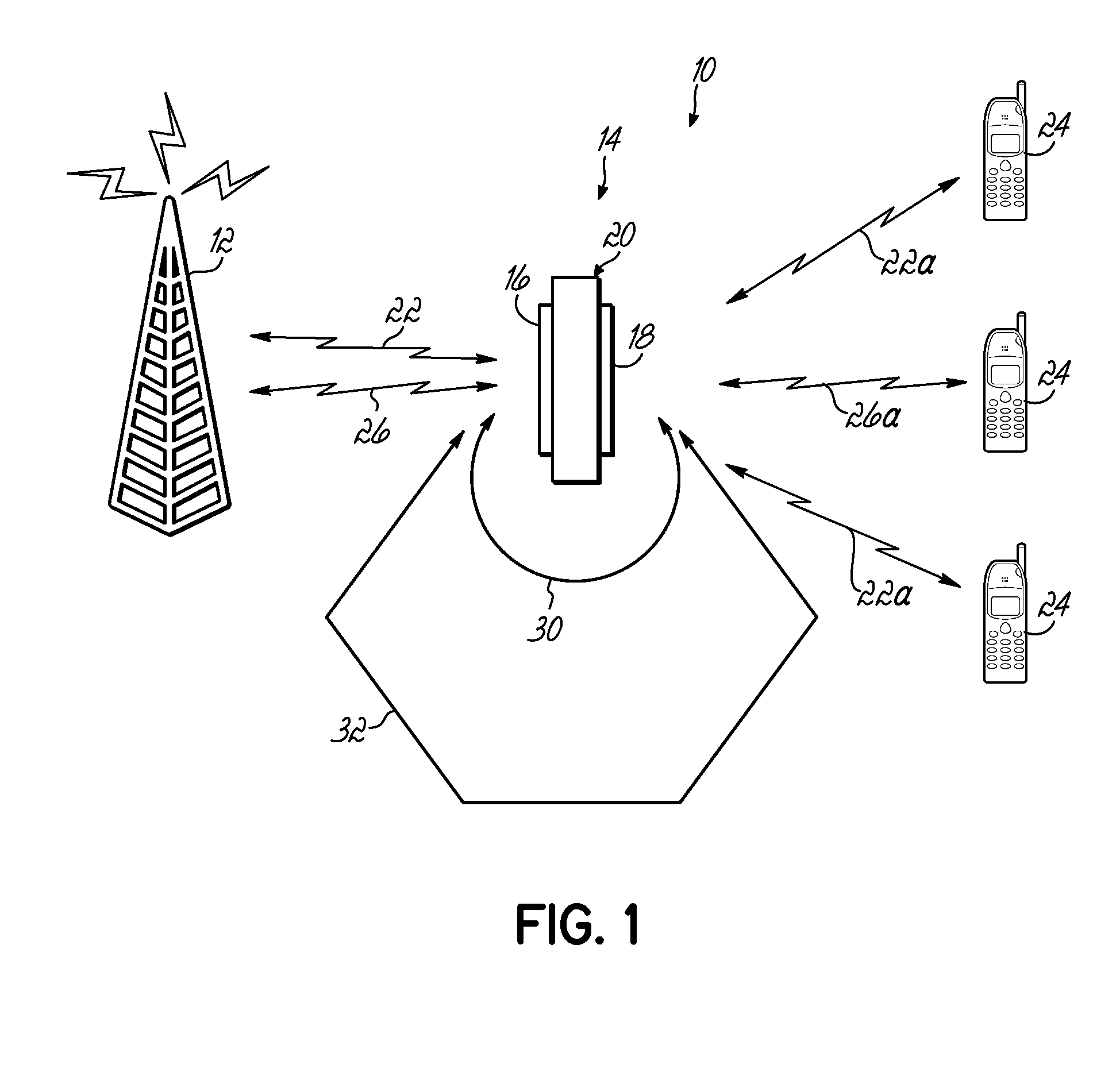
a repeater and gain margin technology, applied in the field of repeaters or signal repeating devices, can solve the problems of repeater oscillation due to feedback signals, another costly and large base station, and limit the performance of the repeater

Active Publication Date: 2011-06-16
COMMSCOPE TECH LLC
View PDF60 Cites 15 Cited by
  • Summary
  • Abstract
  • Description
  • Claims
  • Application Information

AI Technical Summary

Problems solved by technology

Rather than implementing another costly and large base station to provide coverage to such low signal areas, repeaters are utilized.
However, in a non-translating repeater, the isolation between the two opposing antennas or sets of antennas can limit the performance of the repeater.
If there is insufficient attenuation or isolation between the transmit side output and the receive side input, then the repeater can oscillate due to the feedback signals.
This causes significant performance problems.
However, while such a gain margin determination and gain setting may be sufficient at initial installation, such an installation methodology for providing stability in a repeater is not adaptive.
That is, the initial settings and gain margin do not take into account or accommodate any changes in the antenna isolation or any changes in the gain of the repeater.
However, in a non-translating repeater, a problem with separating the signals arises because the input signal and the feedback signal are essentially the same signal with the same frequency.
However, during such a solution, the input repeater signal is not transmitted during the time of the test signal.
This causes a momentary and undesirable interruption of the service of the repeater.
For example, it might lead to dropped calls or other service interruptions in the coverage area of the repeater.

Method used


Image

  • System and method for determining and controlling gain margin in an RF repeater
  • System and method for determining and controlling gain margin in an RF repeater
  • System and method for determining and controlling gain margin in an RF repeater

Examples


Embodiment Construction

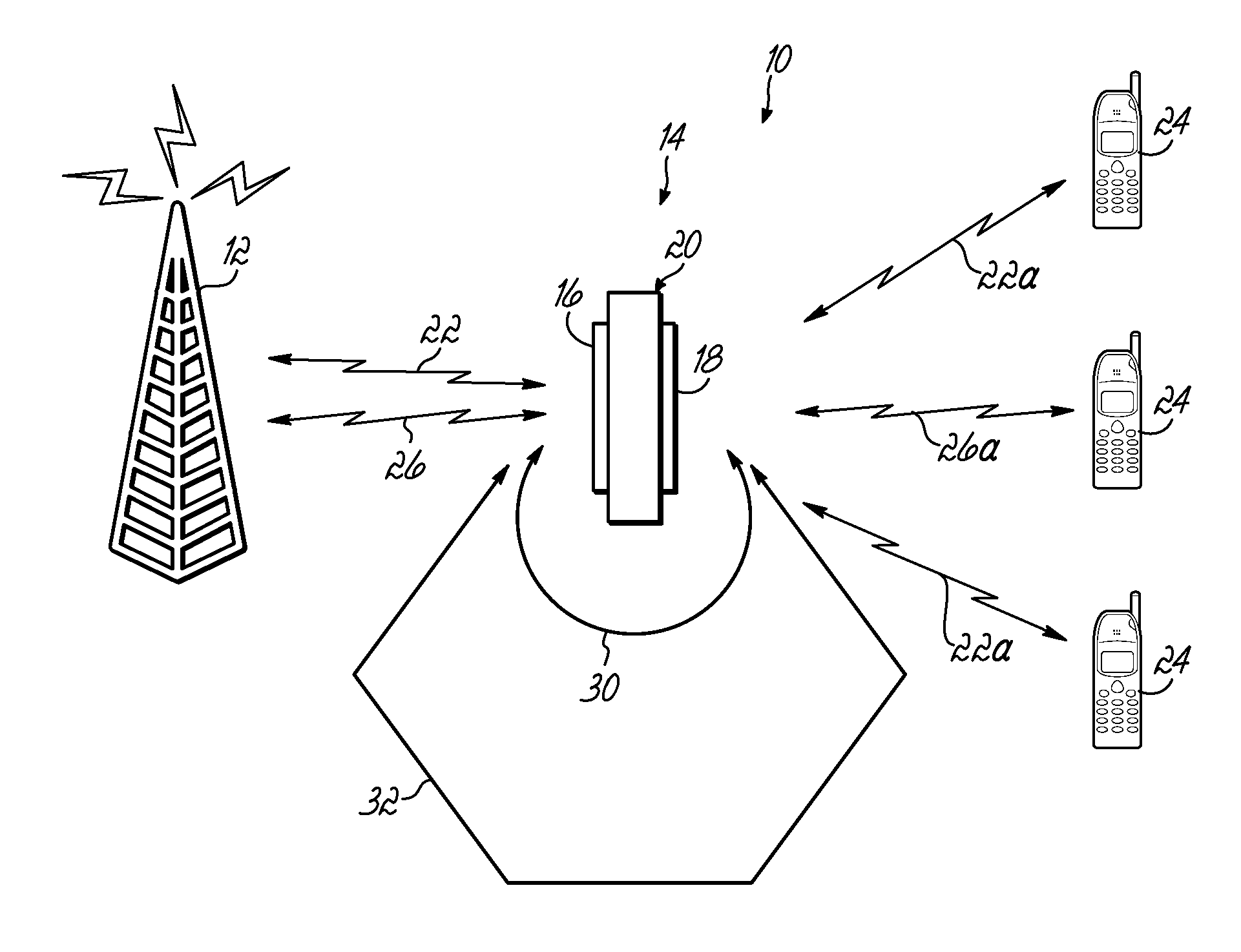
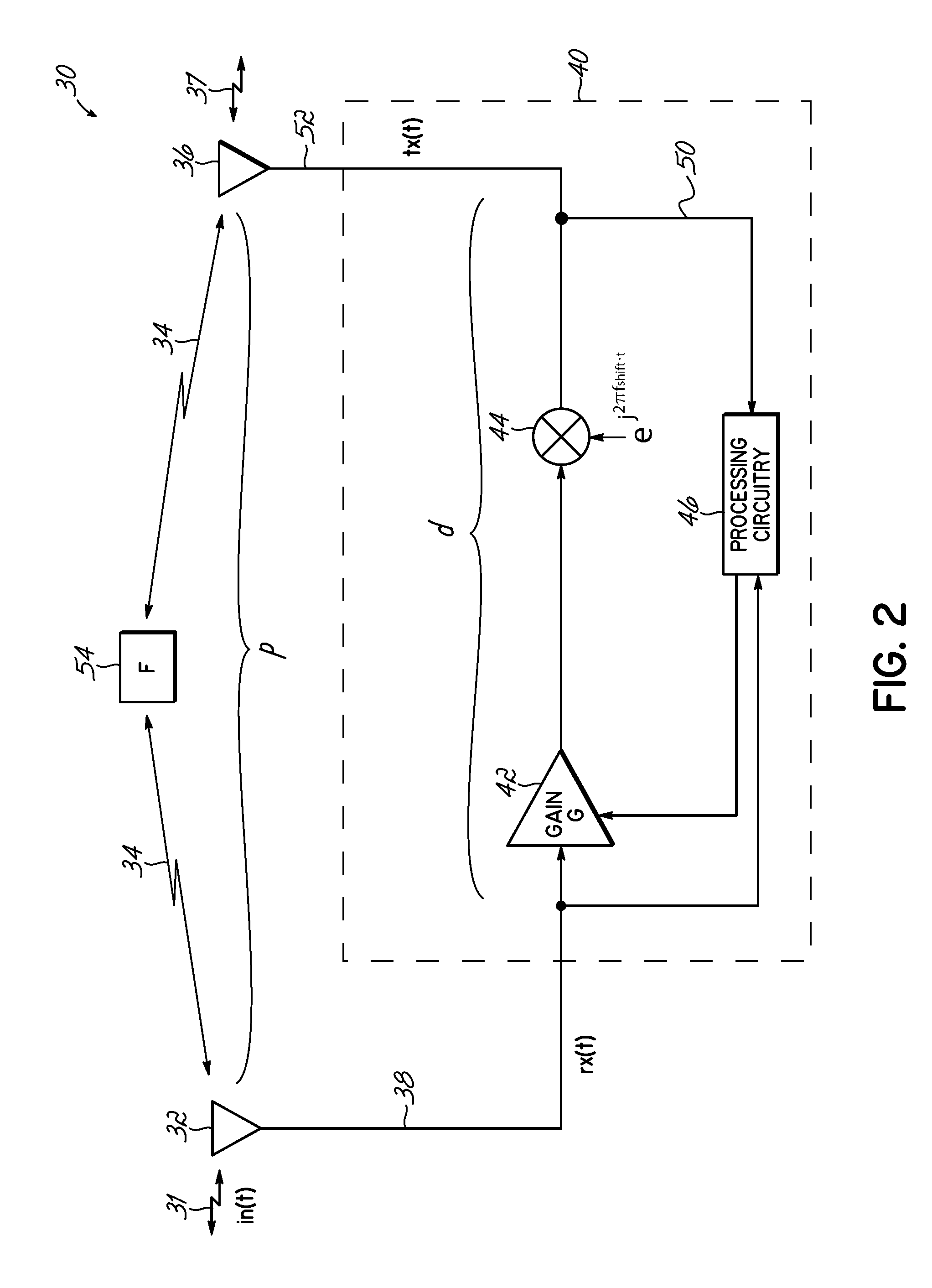
[0016]The present invention provides a signal repeating apparatus, or a repeater that provides adaptive gain adjustment. Particularly, the inventive repeater determines the gain margin of the repeater and uses the measured gain margin to adjust the gain of the repeater to avoid oscillation and instability. The repeater modifies the repeated signals with respect to the receive signals to decorrelate those signals so that the gain margin may be determined. In one embodiment, the modification is made using a frequency shifting circuit to add a frequency shift and provide repeated signals that are slightly frequency-shifted from the input signals originally received by the repeater. Processing circuitry uses the frequency-shifted repeated signals to determine gain margin. The processing circuitry then uses the measured gain margin to adaptively adjust the repeater gain to maintain the desired gain margin to prevent instability.

[0017]Referring to FIG. 2, a schematic block diagram of one ...


PUM


Abstract

An apparatus for repeating signals includes a receive antenna for capturing a receive signal, processing circuitry for processing the receive signal to form a repeated signal, and a transmit antenna for transmitting the repeated signal. The processing circuitry includes gain circuitry for gain in the repeated signal and decorrelation circuitry configured for modifying the repeated signal with respect to the receive signal to thereby decorrelate the repeated signal from the receive signal. The processing circuitry further comprises circuitry configured for calculating a gain margin for the apparatus utilizing the decorrelated receive and repeated signals.

Description

FIELD OF THE INVENTION[0001]The present invention is directed generally to repeaters or signal repeating devices for wireless communications, and more particularly to an apparatus and method for determining and controlling gain margin in signal repeating systems.BACKGROUND OF THE INVENTION[0002]In existing wireless technologies, signal repeating devices, or “repeaters” are used to extend the coverage of the overall wireless system beyond traditional base stations. For example, an overall wireless system may consist of a plurality of base stations that communicate with each other and operate to provide a defined coverage area. In such coverage areas, there are often smaller geographical areas that have very low signal reception with respect to one or more of the base stations. For example, such areas of low signal coverage may be within buildings or areas that are otherwise obstructed. Rather than implementing another costly and large base station to provide coverage to such low sign...

Claims


Application Information

Patent Timeline
IPC IPC(8): H04B7/165
CPCH04B7/15578
Inventor HANSON, VANRANSON, CHRISTOPHER
Owner COMMSCOPE TECH LLC
Learn More