
Control apparatus for rotating electric machine

Active Publication Date: 2017-11-16
DENSO CORP
View PDF0 Cites 5 Cited by
  • Summary
  • Abstract
  • Description
  • Claims
  • Application Information

AI Technical Summary

Benefits of technology

The control apparatus described in this patent aims to prevent a decrease in torque control during phase amplitude control. The apparatus uses a feedback control system with two loops to achieve this. The phase feedback gain and the amplitude feedback gain are set based on certain conditions to ensure good torque controllability. These conditions include ensuring the margin and phase margin in the frequency characteristics of each loop transfer function, as well as the intersection angular frequency in each transfer function. By implementing these feedback gains, the apparatus improves torque control and prevents a decrease in torque controllability during phase amplitude control.

Problems solved by technology

In cases in which phase amplitude control is performed, interference may occur between command current control based on the voltage amplitude and torque control based on the voltage phase.

Method used


Image

  • Control apparatus for rotating electric machine
  • Control apparatus for rotating electric machine
  • Control apparatus for rotating electric machine

Examples


first embodiment

[0037]A first embodiment implementing a control apparatus of the present disclosure will hereinafter be described with reference to the drawings. The control apparatus according to the present embodiment is applied to a three-phase inverter that is connected to a three-phase rotating electric machine. The control apparatus and the rotating electric machine are mounted to a vehicle, such as an electric car or a hybrid car.

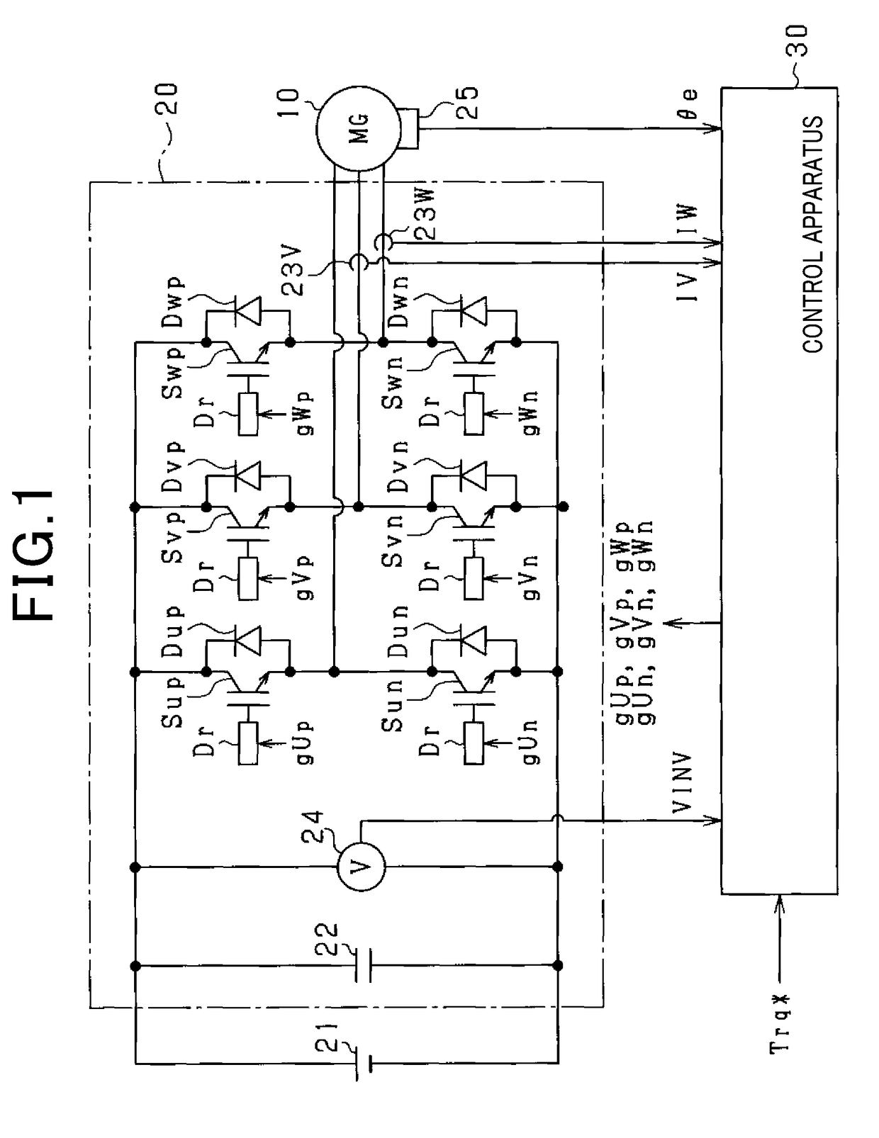
[0038]As shown in FIG. 1, a motor control system includes a motor generator 10, a three-phase inverter 20, and a control apparatus 30. According to the present embodiment, the motor generator 10 is an on-board main machine. A rotor (not shown) of the motor generator 10 is capable of performing power transmission with a drive wheel. According to the present embodiment, a synchronous motor is used as the motor generator 10. More specifically, an interior permanent magnet synchronous motor (IPMSM) is used.

[0039]The motor generator 10 is connected to a battery 21, via t...

second embodiment

[0136]A second embodiment will be described below, with reference to the drawings. The description mainly focuses on the differences from the above-described first embodiment. According to the present embodiment, the setting technique of the feedback gains is modified.

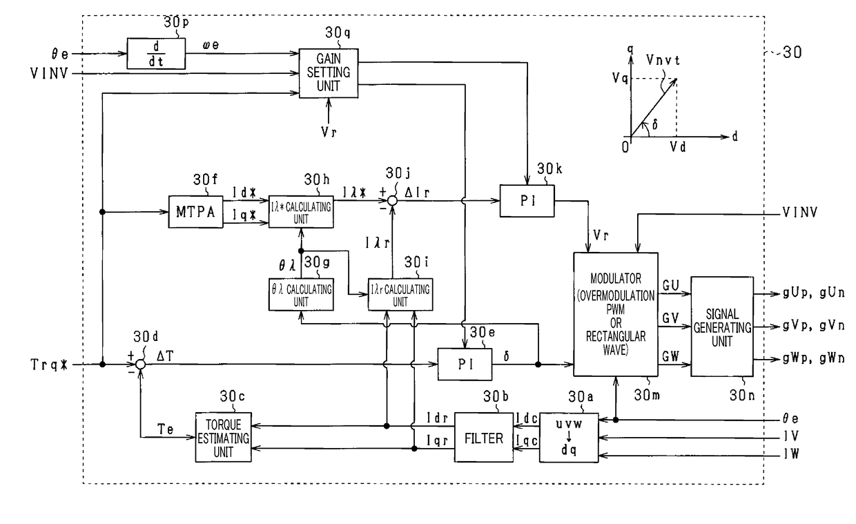
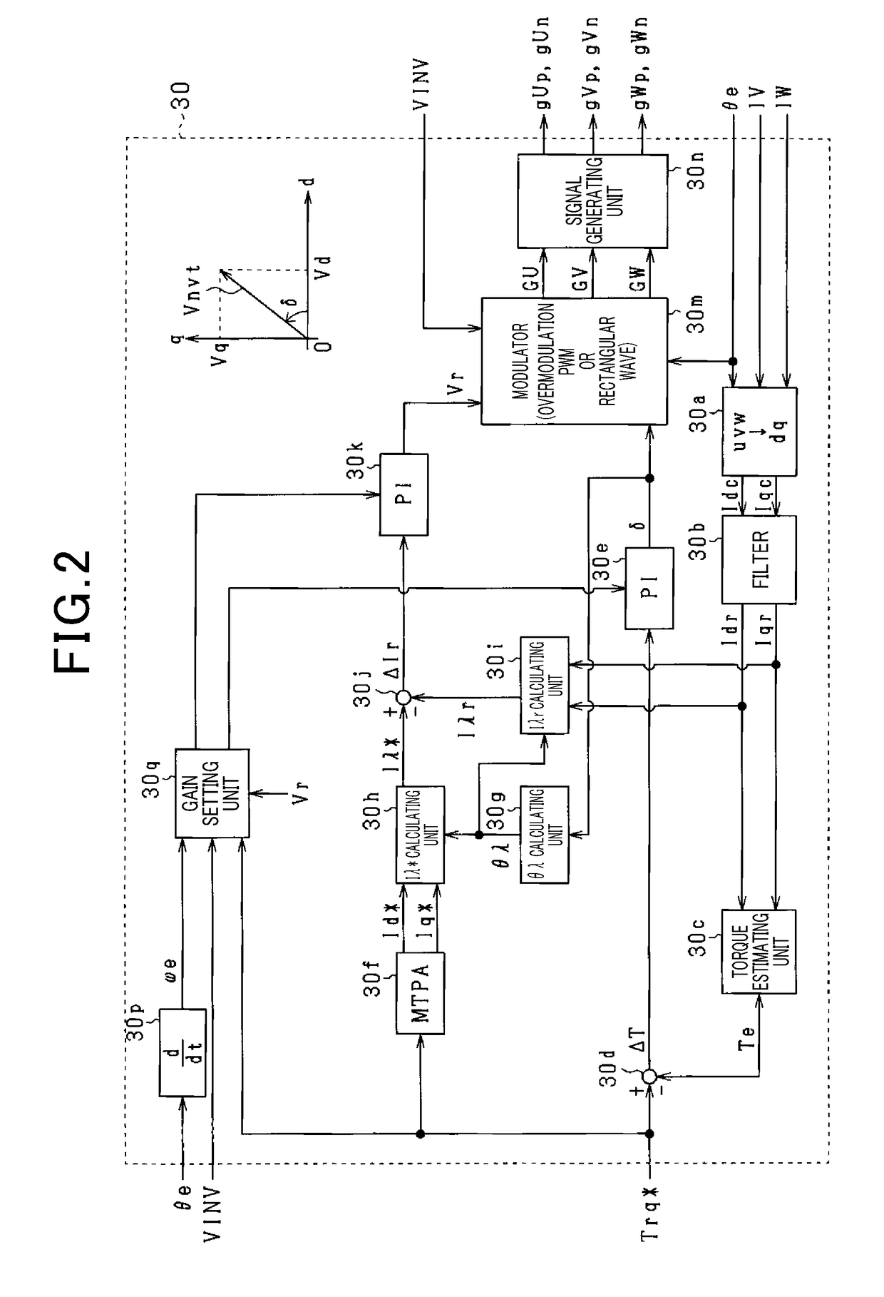
[0137]FIG. 14 shows a functional block diagram of torque control according to the present embodiment. In FIG. 14, configurations that are the same as the above-described configurations shown in FIG. 2 are given the same reference numbers for convenience.

[0138]As shown in FIG. 14, a gain setting unit 30r includes a memory that serves as a storage unit. As shown in FIGS. 15A and 15B, the memory stores therein, in advance, map information prescribing the first proportional gain Kpδ and the first integral gain Kiδ in association with the command torque Trq*, the electrical angular frequency ωe, and the power supply voltage VINV. The first proportional gain Kpδ and the first integral gain Kiδ stored in the memory are adapte...

third embodiment

[0150]A third embodiment will be described below with reference to the drawings. The description mainly focuses on differences from the above-described second embodiment. According to the present embodiment, a storage mode for storing the feedback gains in the memory is modified. Specifically, as shown in FIGS. 17A and 17B, the memory stores therein, in advance, map information prescribing the first proportional gain Kpδ and the first integral gain Kiδ in association with ratio information expressed by VINV / ωe and the command torque Trq*. The ratio information expressed by VINV / ωe is a value obtained by the power supply voltage VINV being divided by the electrical angular frequency ωe. The memory also stores therein, in advance, map information prescribing the second proportional gain Kpv and the second integral gain Kiv in association with the ratio information and the command torque Trq*. In particular, according to the present embodiment, map information of only the feedback gain...


PUM


Abstract

In a control apparatus for a rotating electric machine, a phase feedback gain is set such that first and second conditions are met. The first condition is that gain margin and phase margin in frequency characteristics of a first loop transfer function are ensured. The second condition is that a gain intersection angular frequency in frequency characteristics of the first loop transfer function is lower than respective resonance angular frequency in frequency characteristics of first and second transfer functions. An amplitude feedback gain is set such that third and fourth conditions are met. The third condition is that gain margin and phase margin in frequency characteristics of a second loop transfer function are ensured. The fourth condition is that a gain intersection angular frequency in frequency characteristics of a second loop transfer function is lower than respective resonance angular frequency in frequency characteristics of third and fourth transfer functions.

Description

CROSS-REFERENCE TO RELATED APPLICATION[0001]This application is based on and claims the benefit of priority from Japanese Patent Application No. 2016-097452, filed May 13, 2016. The entire disclosure of the above application is incorporated herein by reference.BACKGROUNDTechnical Field[0002]The present disclosure relates to a control apparatus for a rotating electric machine that is electrically connected to an inverter.Related Art[0003]As this type of control apparatus, a control apparatus that performs phase control to operate an inverter based on voltage phase is known. The voltage phase is the phase of a voltage vector of a voltage supplied to a rotating electric machine. Thus, feedback control is performed to control the torque of the rotating electric machine to a command torque. Here, a method disclosed in JP-A-2012-39730 is known as a method for setting feedback gain used in feedback control. This method uses a model of a single-input single-output rotating electric machine ...

Claims


Application Information

Patent Timeline
IPC IPC(8): H02P21/05H02P6/08H02P6/15
CPCH02P21/05H02P6/085H02P6/15H02P27/06H02P21/0003
Inventor IRIE, KOJI
Owner DENSO CORP
Learn More