Cover unit and printer

Active Publication Date: 2011-06-23
SEIKO EPSON CORP
View PDF9 Cites 11 Cited by
  • Summary
  • Abstract
  • Description
  • Claims
  • Application Information

AI Technical Summary

Problems solved by technology

The printer cover and lever therefore twist or bend when being pu

Method used


Image

  • Cover unit and printer
  • Cover unit and printer
  • Cover unit and printer

Examples


Embodiment Construction

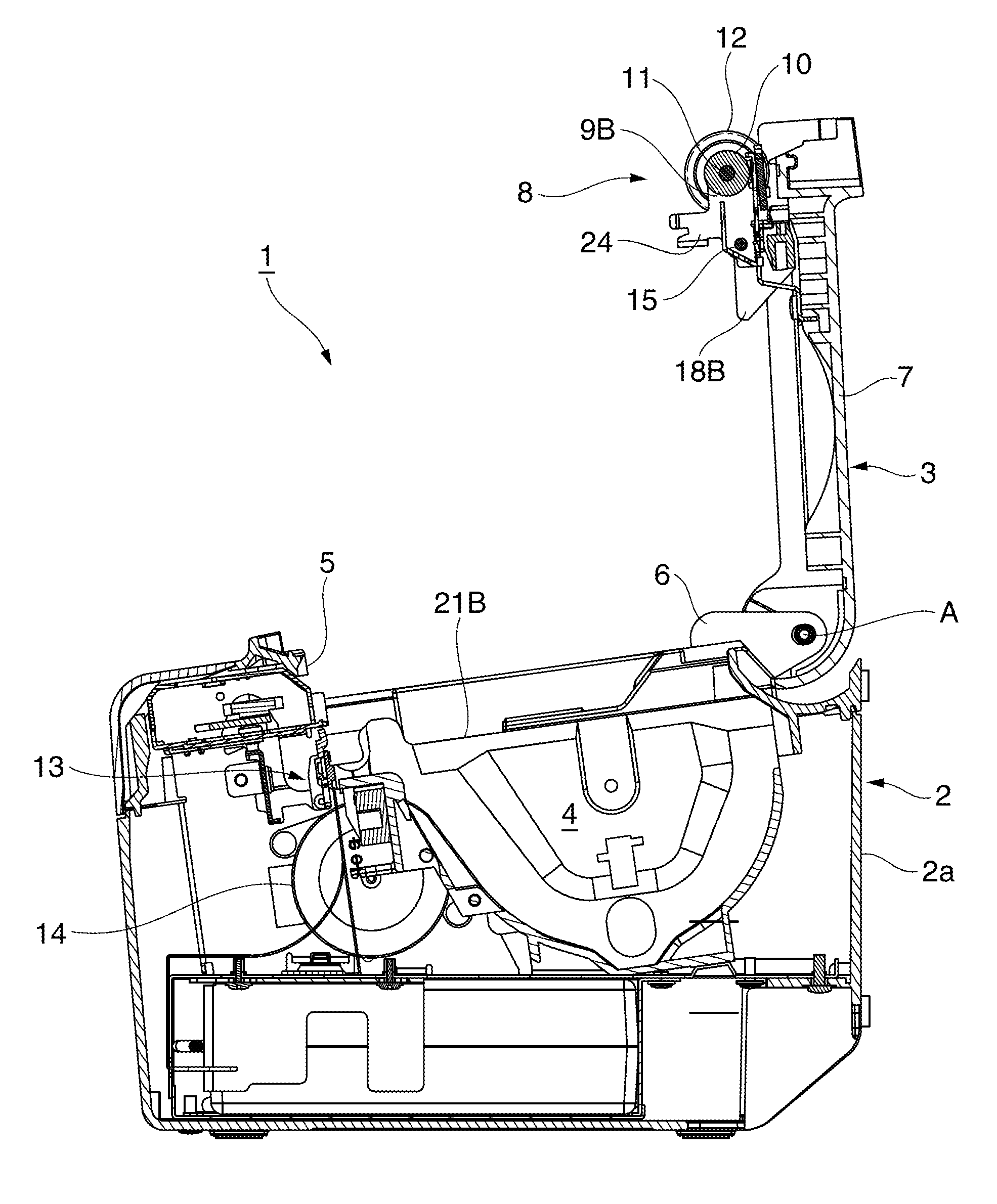
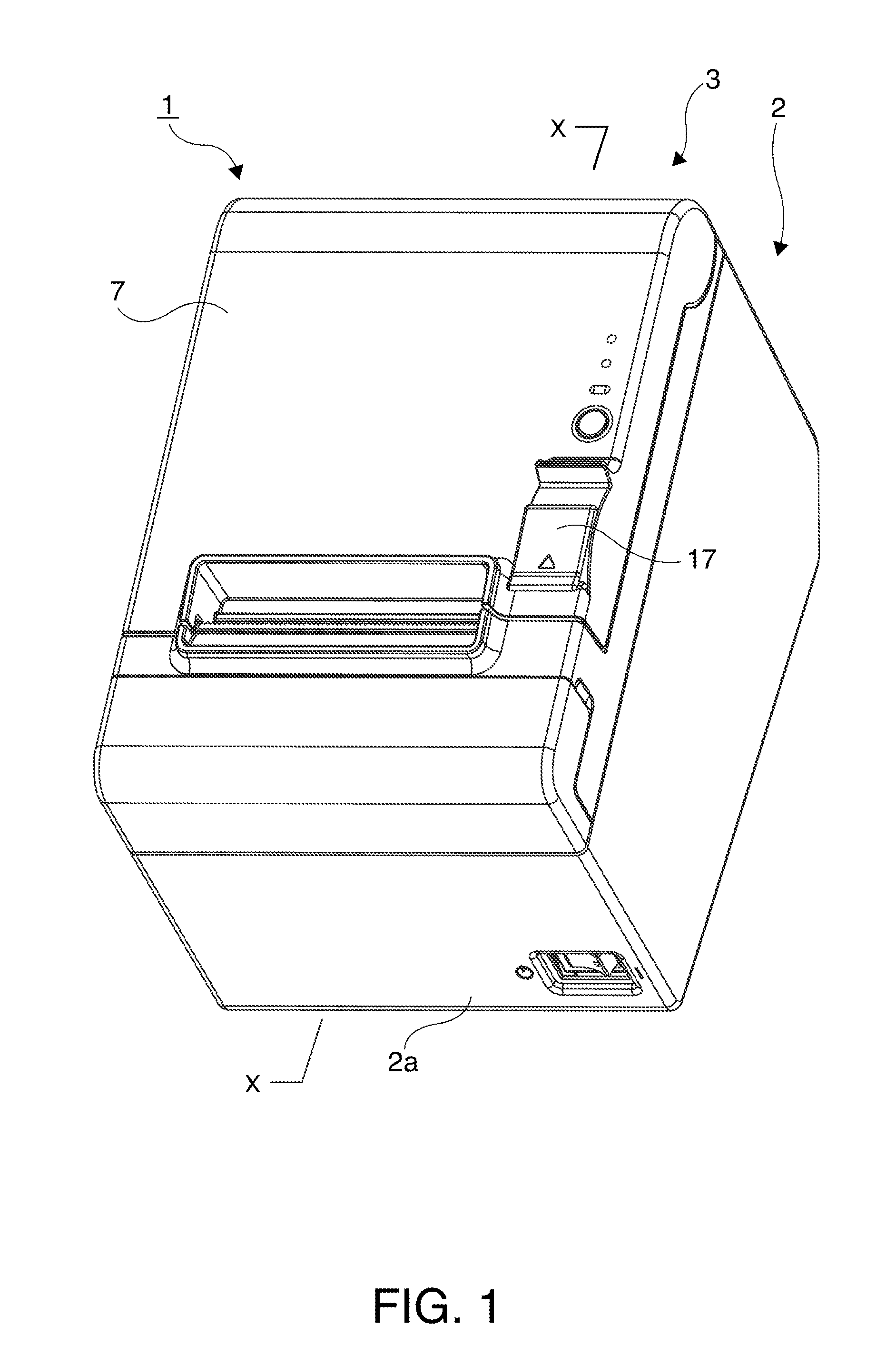
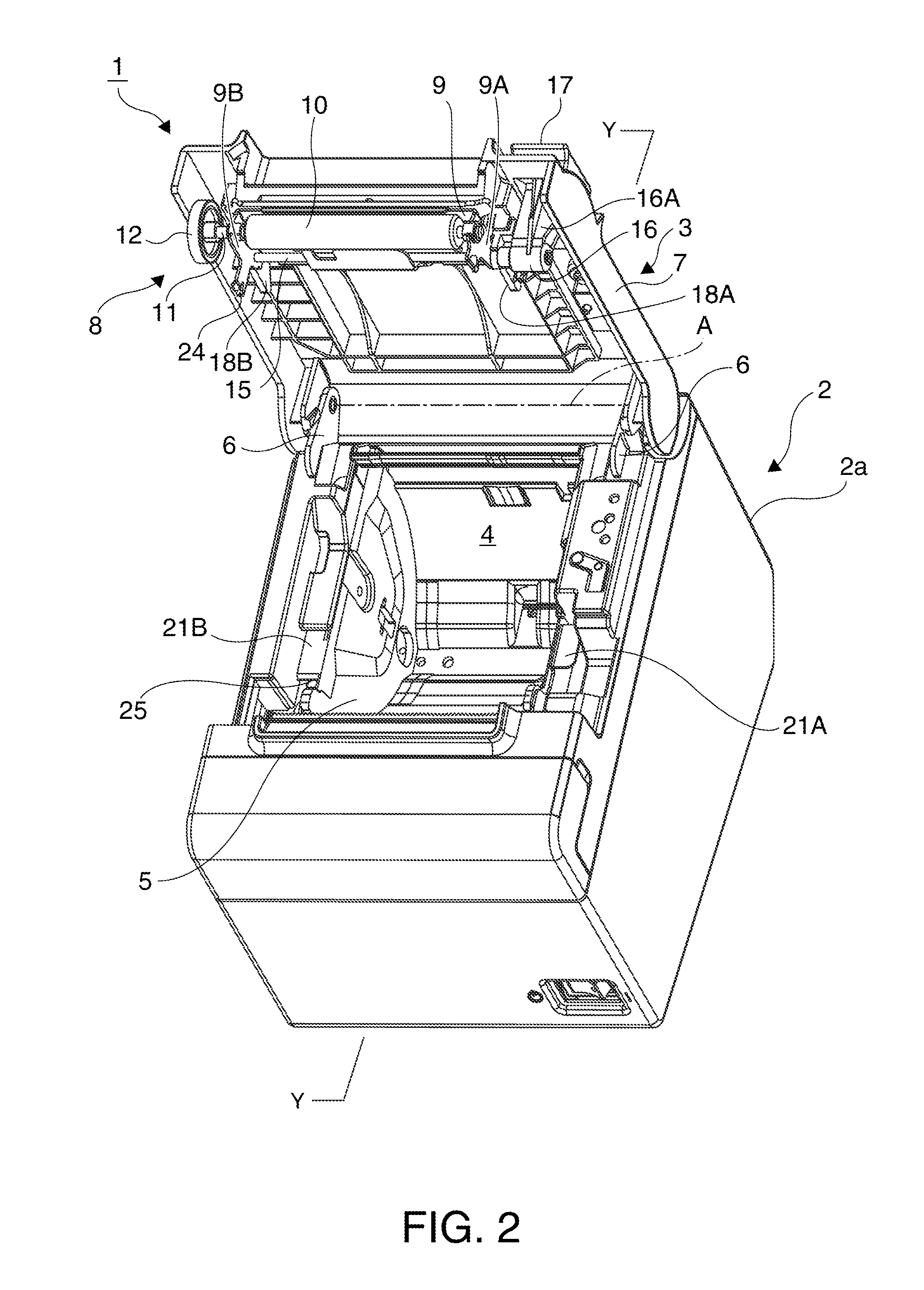
[0031]Preferred embodiments of a cover unit and a printer having a cover unit according to the present invention are described below with reference to the accompanying figures. FIG. 1 is an external oblique view of the printer with the cover unit closed, and FIG. 2 is an external oblique view of the printer with the cover unit open. FIG. 3 is a section view of the printer with the cover unit closed as seen through line X-X in FIG. 1, and FIG. 4 is a section view of the printer with the cover unit open as seen through line Y-Y in FIG. 2. General configuration

[0032]As shown in FIG. 1 to FIG. 4, the printer 1 has a housing 2 and a cover unit 3 attached to the top of the housing 2. The printer 1 in this embodiment of the invention is a thermal printer, and a roll paper compartment 4 in which the roll paper is loaded is rendered inside the case member 2a of the housing 2. An opening 5 for loading and removing roll paper is formed in the case member 2a above the roll paper compartment 4. ...


PUM


Abstract

One end of the cover unit of a printer is supported freely rotatably on the device case, and a rotating shaft is disposed with both ends supported freely rotatably on the distal end. A right pressure lever and an operating lever are supported on the right end of the rotating shaft, and a left pressure lever is supported on the left end. When the operating lever rotates, the right and left pressure lever rotate in the same direction through an intervening rotation transfer member extending widthwise to the device. When the operating lever rotates when the cover is closed, the left pressure lever contacts the device case before the right pressure lever . The right and left pressure lever are set so that their rotational positions are the same when the cover starts to rise due to deformation of the rotation transfer member.

Description

BACKGROUND[0001]1. Technical Field[0002]The present invention relates to a cover unit that accomplishes a cover opening operation lifting an access cover open from a closed position as a result of operating a lever disposed on one widthwise side of the access cover, one end of which is supported freely pivotably on the case of a printer, and relates to a printer having this cover unit.[0003]2. Related Art[0004]In order to load roll paper into the internal roll paper compartment of a thermal printer or other type of roll paper printer, an opening through which the roll paper can be inserted and removed is formed in the printer case. A cover unit that opens and closes the opening to the roll paper compartment is disposed with one end of an access cover supported freely pivotably on an edge of this opening so that the access cover can swing open and closed pivoting on this end.[0005]Japanese Unexamined Patent Appl. Pub. JP-A-2004-276521 teaches such a thermal printer. The thermal print...

Claims


Application Information

Patent Timeline
IPC IPC(8): E06B3/38
CPCB41J29/13B41J29/02
Inventor YAMADA, MASAHIKO
Owner SEIKO EPSON CORP
Why Eureka
Try Eureka