Filament winding system
a technology of winding system and filament, which is applied in the direction of mechanical equipment, vessel construction details, other domestic objects, etc., can solve problems such as winding error, reduce computation load, reduce or eliminate the difference, and reduce or eliminate the winding error of fiber
- Summary
- Abstract
- Description
- Claims
- Application Information
AI Technical Summary
Benefits of technology
Problems solved by technology
Method used
Image
Examples
first embodiment
A. First Embodiment
A1. Configuration of Winding Object
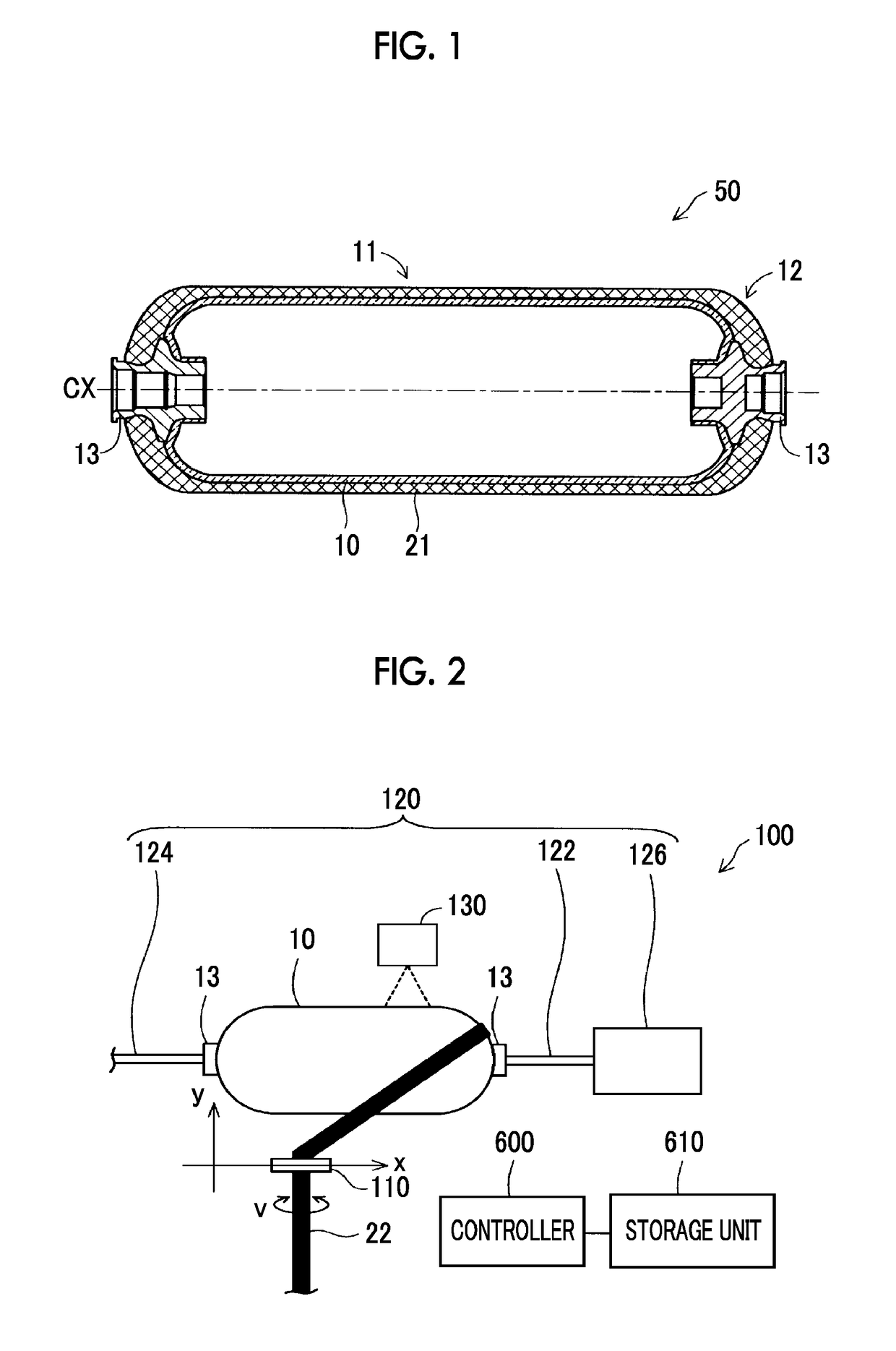
[0017]FIG. 1 is a schematic cross-sectional view of a tank 50 used in a first embodiment. The schematic cross-sectional view of FIG. 1 shows the tank 50 at the time when the tank 50 is cut along a cutting plane that passes its center axis CX. In this embodiment, a liner 10 is used as a winding object, and the tank 50 is a gas tank used for a fuel cell.
[0018]The tank 50 includes the liner 10 having cap portions 13, and a fiber layer 21. The liner 10 is an airtight container that contains gas to be supplied to the fuel cell. The liner 10 includes a generally cylindrical body portion 11 formed in a central portion thereof, and generally semispherical dome portions 12 formed continuously from the opposite ends of the body portion 11. As a material of the liner 10, a high-strength aluminum material or stainless material, or a resin material may be used.
[0019]The cap portions 13 are provided at distal ends of the dome portions 12, and ...
second embodiment
B. Second Embodiment
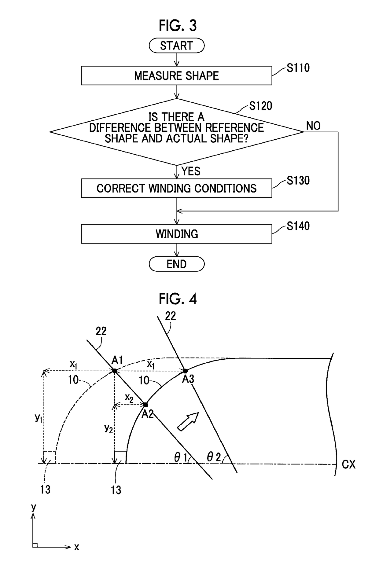
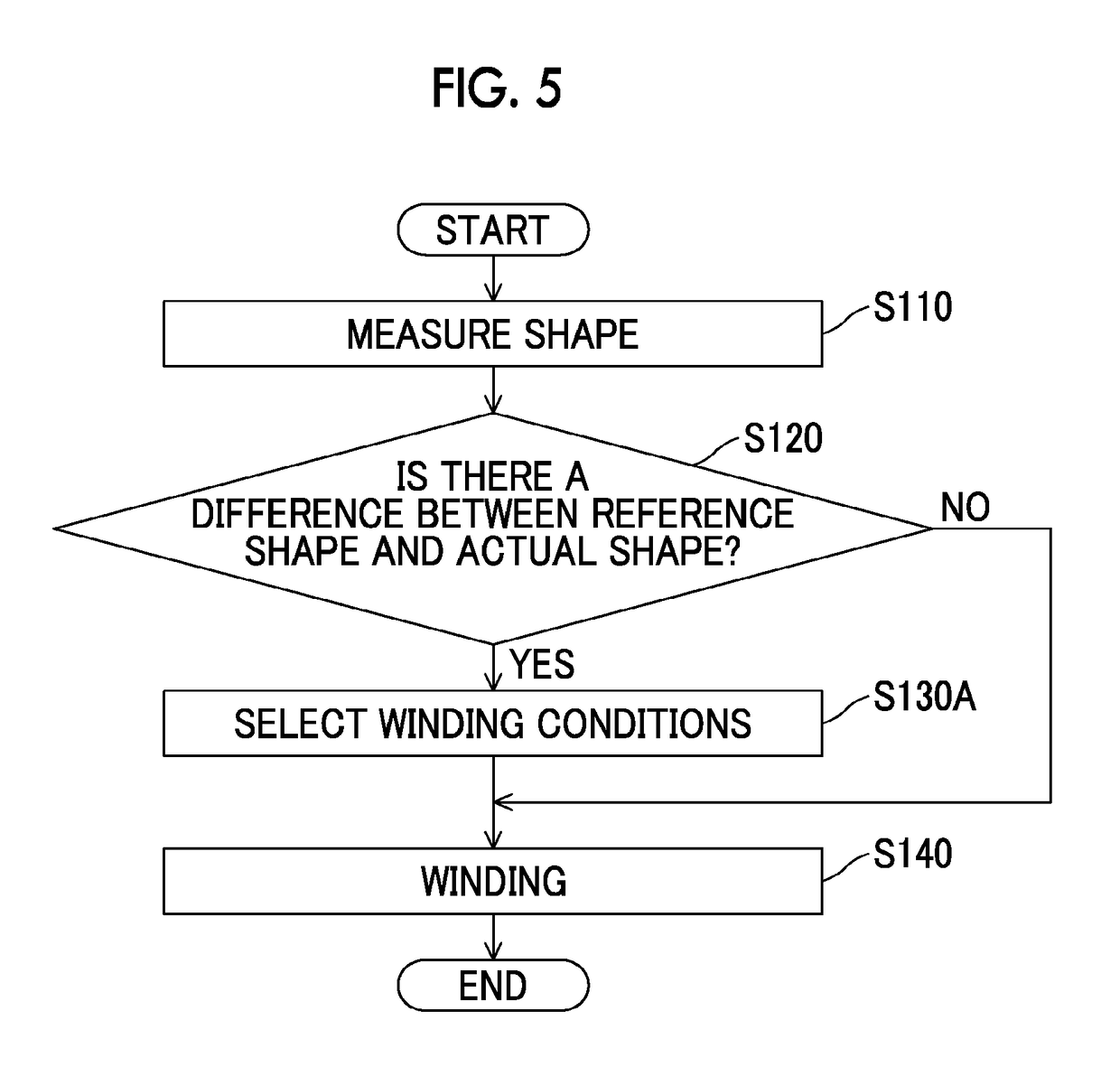
[0034]FIG. 5 is a flowchart illustrating a control routine of a second embodiment. A filament winding system of the second embodiment is different from that of the first embodiment in that a plurality of sets of winding conditions corresponding to differences between the reference shape and the actual shape are further stored in the storage unit 610; however, the system of the second embodiment is identical with that of the first embodiment in other respects. Also, the control routine of the second embodiment is different from that of the first embodiment in that the routine includes step S130A, in place of step S130, but the control routine of the second embodiment is identical with that of the first embodiment in other respects.
[0035]Here, the winding conditions corresponding to a difference between the reference shape and the actual shape include, for example, winding conditions that the winding position is position A3, and the winding angle is θ2, when the wi...
third embodiment
C. Third Embodiment
[0038]FIG. 6 is a flowchart illustrating a control routine of a third embodiment. A filament winding system of the third embodiment is different from that of the first embodiment in that (i) an n-layer reference shape as a shape obtained after the fiber 22 is wound around the liner 10 having the reference shape to form “n” layers (“n” is a positive integer) of the fiber 22, and (ii) (n+1)-layer winding conditions including the winding position at which the fiber 22 is wound around the liner 10 having the n-layer reference shape, are further stored in advance in the storage unit 610, but the system of the third embodiment is identical with that of the first embodiment in other respects. Also, the control routine of the third embodiment is difference from that of the first embodiment in that the routine includes step S140A in place of step S140, and further includes step S150 to step S190; however, the control routines of the first and third embodiments are identica...
PUM
| Property | Measurement | Unit |
|---|---|---|
| distance | aaaaa | aaaaa |
| winding angle | aaaaa | aaaaa |
| shape | aaaaa | aaaaa |
Abstract
Description
Claims
Application Information
 - R&D
- Intellectual Property
- Life Sciences
- Materials
- Tech Scout
- Unparalleled Data Quality
- Higher Quality Content
- 60% Fewer Hallucinations
Browse by: Latest US Patents, China's latest patents, Technical Efficacy Thesaurus, Application Domain, Technology Topic, Popular Technical Reports.
© 2025 PatSnap. All rights reserved.Legal|Privacy policy|Modern Slavery Act Transparency Statement|Sitemap|About US| Contact US: help@patsnap.com


