Eureka AIR delivers breakthrough ideas for toughest innovation challenges, trusted by R&D personnel around the world.

Control method and device for engine

a control method and engine technology, applied in electrical control, program control, instruments, etc., can solve problems such as deviation from the optimization of the testing bench, inability to achieve a complete correction, and decrease in control accuracy, so as to reduce or eliminate errors, improve control precision and speed, and enhance real-time characteristics of control

Inactive Publication Date: 2013-05-28
SHANDONG SHENPU TRAFFIC TECHNOLOGY CO LTD
View PDF8 Cites 7 Cited by
  • Summary
  • Abstract
  • Description
  • Claims
  • Application Information

AI Technical Summary

Benefits of technology

[0014]The technical problem to be solved of the present invention is to provide a strategy, by which the dynamic parameter maps can be adaptively generated according to the change of the engine associated characteristics and the change of the engine usage conditions during a working process, aiming at the existing problems in the current control ways of the gasoline engine; thereby to provide a method and a device, which utilizes the combined parameter maps obtained by combining the dynamic parameter maps with the original basic parameter maps to control the engine.
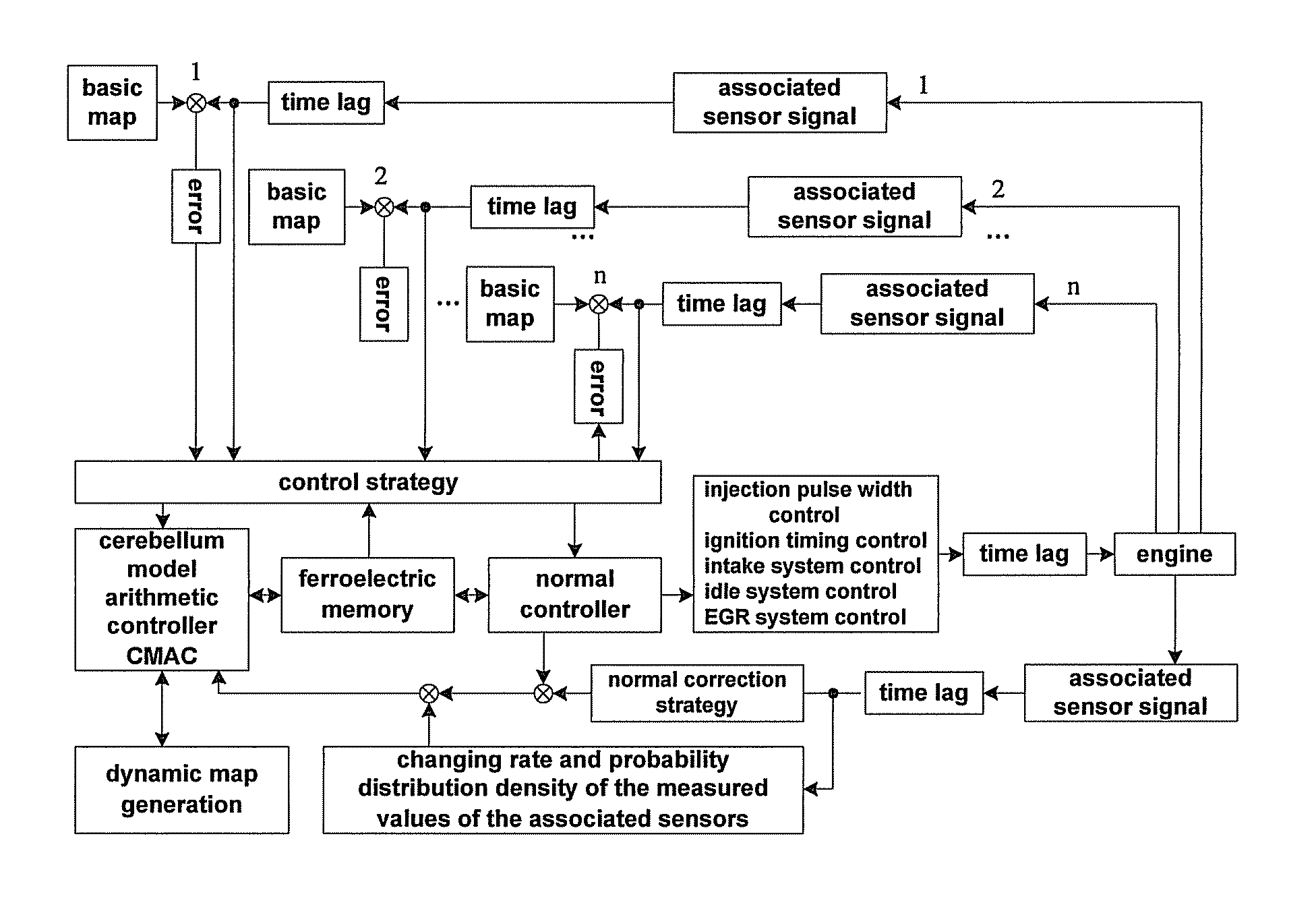
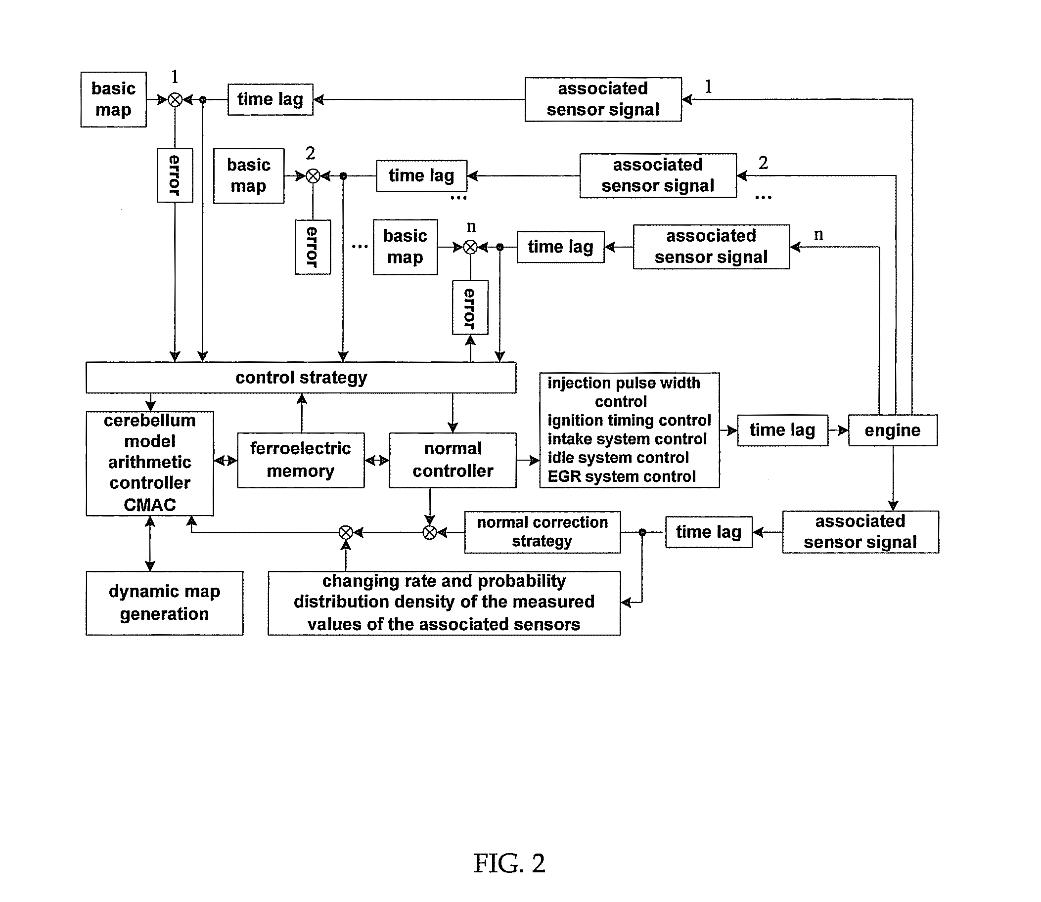
[0035]In one aspect, the control system determines the trend of working status change based on the changing rate of the feature signals of the associated sensors of the engine to perform predictive control of the given target values on a portion of the control targets with too much deviation of time lag. Meantime, it also utilizes the adaptive adjusting and learning ability of the cerebellum model arithmetic controller CMAC to reduce or eliminate the errors caused by the signal lags of various aspects with the predictive control target values as a data node.
[0036]In another aspect, when compared with the existing techniques, the method of the present invention which controls the engine with the combined maps has the following beneficial effects. Since the combined parameter map control way is adopted, which is combined with adaptive learning method, the effects to the engine due to the change and uncertain change of the controlled system are corrected, thereby, the control precision and speed is improved. Also, the programming and generation of the dynamic parameter maps is used to improve the problem that the control system can not respond when the condition of the engine itself changes. The control is predicted ahead via the strategy of generating the dynamic parameter maps by the adaptive learning control, by which the control lags caused by the various time lag effects are corrected with utmost and the real time characteristic of the control is enhanced.

Problems solved by technology

(1) decreased control accuracy because of manufacture deviation associated with sensors and executable devices, variations in working characteristics due to abrasion and aging after a period of usage, matching deviation due to fittings replacements, and others;
(2) varied loads because of environment and season changes, working mediums changes (such as a machine oil viscosity change), electric appliances and auxiliary power access changes, and different operation of the engine;
(3) deviated measurements caused by measuring instruments and operating means used in optimizing the control unit on an engine testing bench, and other uncertain factors that are unconsidered;
(4) deviated real-time controls caused by signal transfer time lag of the sensors, operation process time lag of the control unit, movement time lag of the executable devices, and others.
The aforementioned problems affect the controlled targets resulting in deviation from the testing bench optimizations for the basic ignition parameter maps, the basic injection parameter maps and other controlled parameter maps.
However, due to various time lag effects, one can only partially correct control deviation in correspondence to various condition signals fed back by the sensors, but cannot achieve a complete correction.
Consequently, the engine is not able to operate efficiently.

Method used


Image

  • Control method and device for engine
  • Control method and device for engine
  • Control method and device for engine

Examples


Embodiment Construction

[0052]Specific embodiments of the present invention are provided in the following description in detail. It should be noted that the described embodiments are only used for illustration but not to limit the scope of the present invention.

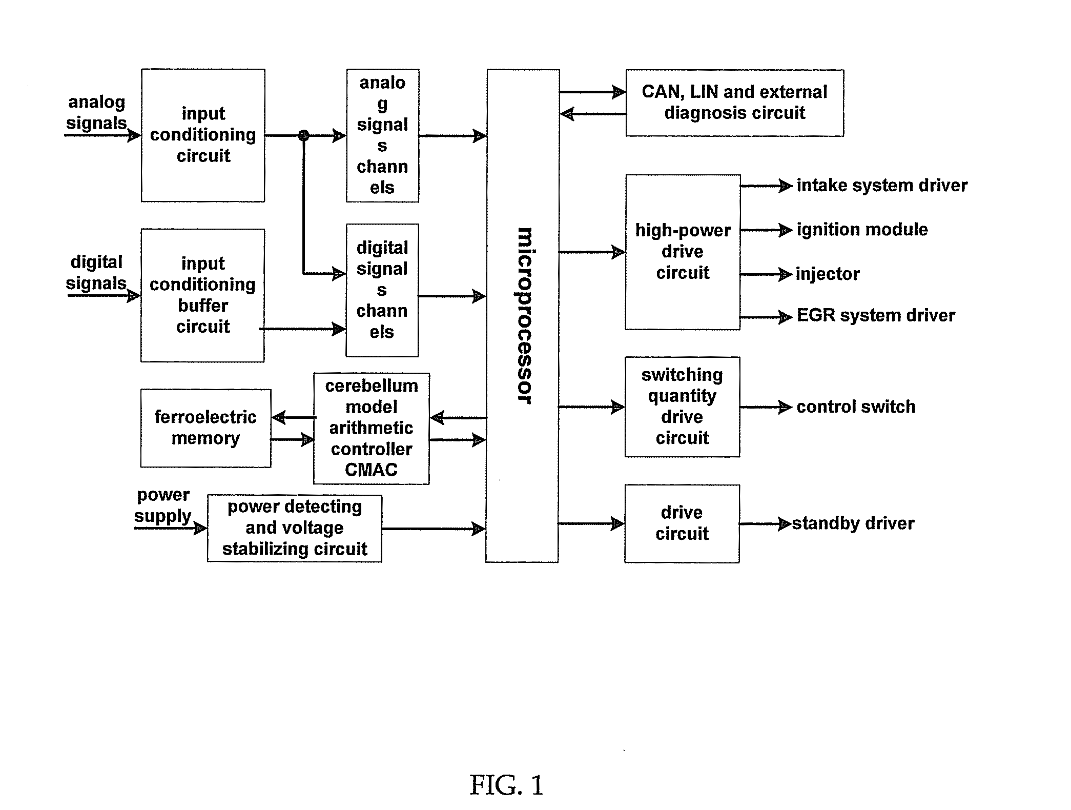
[0053]The control method and device for engine by the combined maps presented by the present invention achieve the control functions for the engine by a normal controller (a central control unit ECU) and the cerebellum model arithmetic controller CMAC based on some control strategies, wherein, the control strategies include a correction strategy, a dynamic map generation strategy and a dynamic map combination strategy, and the control functions include an injection control, an ignition (ignition advance angle and ignition dwell angle) control, an intake control, an idle control, a discharge (a carbon canister evaporation, an exhaust gas recirculation system EGR) control and an auxiliary (electric load, power-assisted steering, oil pump, air-conditio...


PUM


Abstract

A control method and a control device of an engine are introduced. During the process of the engine controlling, the control unit does the adaptive learning for the actual target value of the feedback of different aims, and following the dynamic spectrogram generation strategy optimizing compares the adaptively learning parameter of the same working status and the same time with the basic spectrogram parameter. If the compared result doesn't meet the condition, then keep the basic spectrogram parameter. And if it meets the condition, then the engine generates the dynamic spectrogram parameter. Based on the dynamic spectrogram combination strategy, the engine combines the basic spectrogram parameter and the dynamic spectrogram parameter generated to the combined spectrogram parameter instead of the basic spectrogram parameter.

Description

TECHNICAL FIELD[0001]The present invention relates to a control method and a control device for an engine, which pertains to the technical field of gasoline engine control.BACKGROUND OF THE INVENTION[0002]Main controls for a vehicle gasoline engine include an ignition control and an injector control.[0003]During a control process, a control unit locates controlled parameter maps according to basic control conditions, corrects them based on the engine conditions reflected by a plural of sensors, outputs them to control a plural of actuators, and thus controls targets. The controls are open-loop controls and closed-loop controls.[0004]An open-loop control of engine ignition timing is mainly based on an engine load signal which is determined by an intake flowrate signal and a throttle valve signal, an engine rotational speed signal and a crankshaft position signal. A closed-loop control of engine ignition timing is, based on feedback signals of knock sensor(s), to adjust an ignition sy...

Claims


Application Information

Patent Timeline
Patent Type & Authority Patents(United States)
IPC IPC(8): G06F19/00G06G7/70F02D41/00F02M51/00F02P5/00
CPCF02D41/2422F02D41/2429F02D41/2477G05B13/0245F02D41/1401F02D41/2432F02D41/2454F02D41/26G05B2219/2623Y02T10/40F02D41/14F02D41/04F02D45/00F02D41/02
Inventor GAO, XIAOQUNGONG, CHUNYONGZHAO, HUA
Owner SHANDONG SHENPU TRAFFIC TECHNOLOGY CO LTD
Why Eureka
Eureka Blog
Learn More