Single controller automatic calibrating circuits for reducing or canceling offset voltages in operational amplifiers in an instrumentation amplifier

an instrumentation amplifier and offset voltage technology, applied in the field of instrumentation amplifiers, can solve the problems of increasing the number of active components per unit area, reducing the accuracy of measuring current in one particular area of an ic, and reducing the effect of sensing error

Active Publication Date: 2019-09-17
QUALCOMM INC
View PDF8 Cites 6 Cited by
  • Summary
  • Abstract
  • Description
  • Claims
  • Application Information

AI Technical Summary

Benefits of technology

[0008]Aspects disclosed in the detailed description include single controller automatic calibrating circuits for reducing or canceling offset voltages in operational amplifiers (op-amps) in an instrumentation amplifier. For example, the instrumentation amplifier may be used to sense current distributed to a load circuit to measure power consumption. In this regard, in exemplary aspects disclosed herein, an automatic calibrating op-amp system is provided that includes an instrumentation amplifier. The instrumentation amplifier includes a front-end amplifier circuit comprising at least one front-end op-amp and a final-stage amplifier circuit comprising a final-stage op-amp. The front-end op-amp(s) and the final-stage amplifier circuit may have high input impedance, thus making the instrumentation amplifier particularly suited for use in making measurements, such as power consumption. The front-end op-amp(s) is configured to receive respective input voltages and generate intermediate output voltages according to the respective gain of the front-end op-amp(s). The final-stage op-amp is a differential amplifier that is configured to generate a final-stage output voltage representing a difference in the intermediate output voltages from the front-end op-amp(s). In one example, each of the op-amps in the instrumentation amplifier includes auxiliary differential inputs for offset voltage cancellation to reduce or eliminate sensing error. The automatic calibrating op-amp system also includes an automatic calibration circuit employing a single controller to generate calibration signals on a calibration output to an auxiliary differential input(s) of an op-amp(s) in the instrumentation amplifier for offset voltage cancellation. For example, the automatic calibration circuit may employ a successive approximation register (SAR) controller and digital-to-analog converter (DAC) for converting successive digital values from the SAR controller into the calibration signal. The automatic calibration circuit includes a single controller in examples disclosed herein to generate calibration signals to the instrumentation amplifier to cancel offset voltages to eliminate the need to provide multiple automatic calibration circuits or an automatic calibration circuit employing multiple controllers to cancel offset voltages in the instrumentation amplifier.

Problems solved by technology

Preventing or avoiding excessive current is a problem of increasing concern in integrated circuit (IC) design, particularly because excessive current in an IC can cause circuit failure.
This problem has become especially critical as voltage scaling has slowed down and the number of active components per unit area has increased.
Although the current of the IC may be measured using an on-die current measurement system on a semiconductor die, accurately measuring current within the IC may be difficult.
Thus, measuring current in one particular area of an IC may not provide an accurate representation of overall current within the IC.
Inaccurate current measurements within the IC may reduce the effectiveness of current control functions employed to prevent circuit failures.
A 1 mV one-sigma offset voltage would require large input devices for this level of matching and may be difficult to achieve.

Method used


Image

  • Single controller automatic calibrating circuits for reducing or canceling offset voltages in operational amplifiers in an instrumentation amplifier
  • Single controller automatic calibrating circuits for reducing or canceling offset voltages in operational amplifiers in an instrumentation amplifier
  • Single controller automatic calibrating circuits for reducing or canceling offset voltages in operational amplifiers in an instrumentation amplifier

Examples


Embodiment Construction

[0033]With reference now to the drawing figures, several exemplary aspects of the present disclosure are described. The word “exemplary” is used herein to mean “serving as an example, instance, or illustration.” Any aspect described herein as “exemplary” is not necessarily to be construed as preferred or advantageous over other aspects.

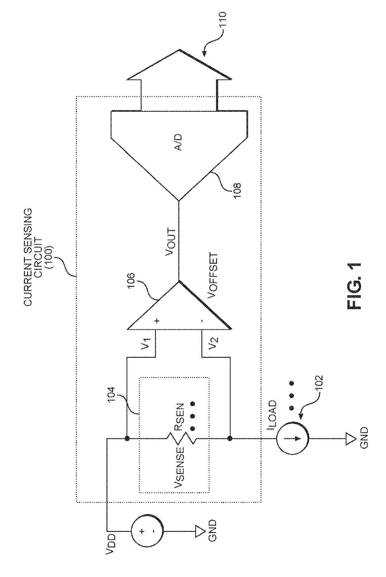
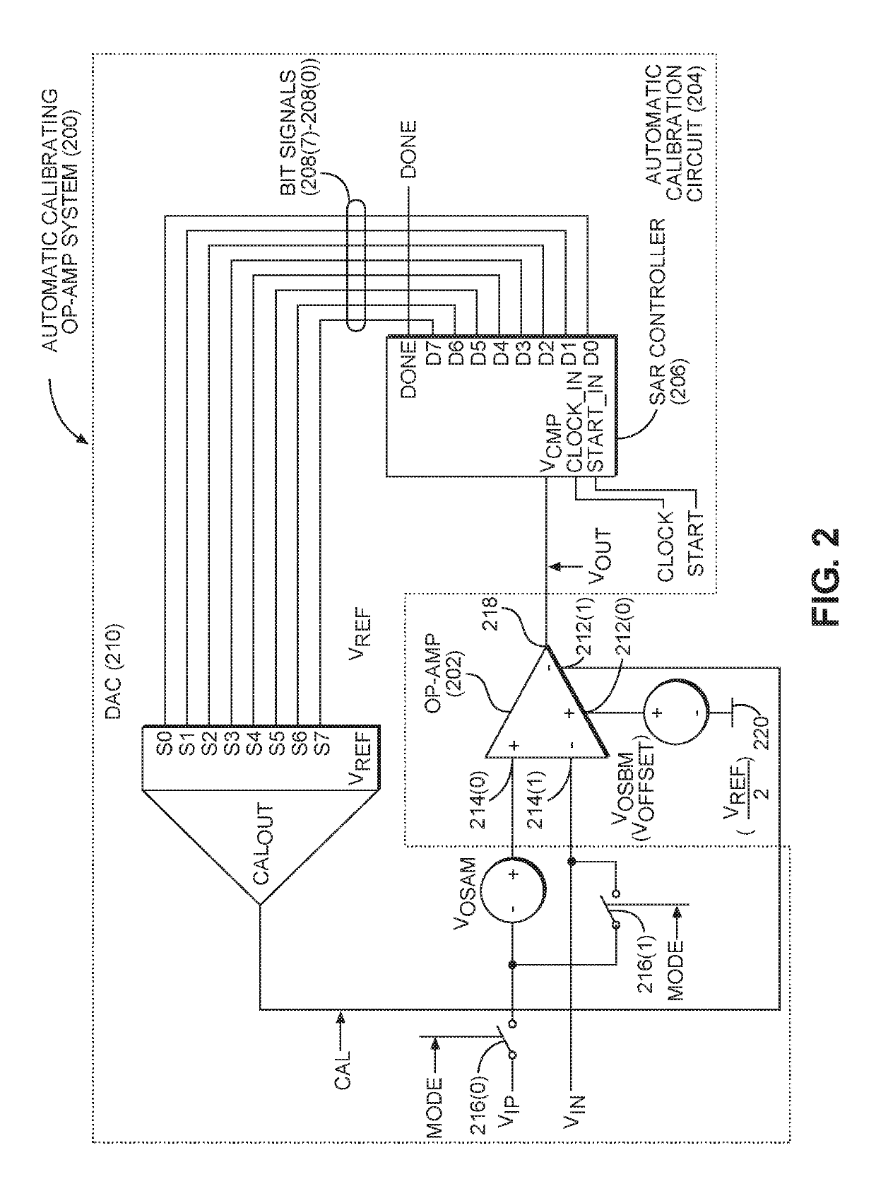
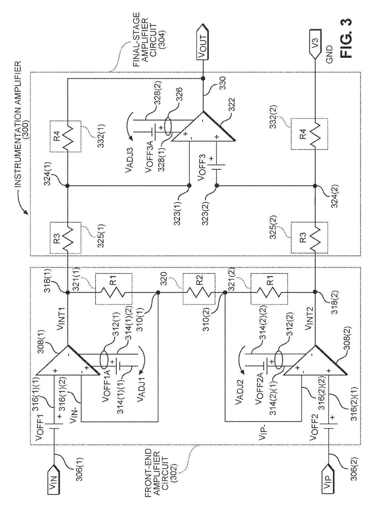
[0034]Aspects disclosed in the detailed description include single controller automatic calibrating circuits for reducing or canceling offset voltages in operational amplifiers (op-amps) in an instrumentation amplifier. For example, the instrumentation amplifier may be used to sense current distributed to a load circuit to measure power consumption. In this regard, in exemplary aspects disclosed herein, an automatic calibrating op-amp system is provided that includes an instrumentation amplifier. The instrumentation amplifier includes a front-end amplifier circuit comprising at least one front-end op-amp and a final-stage amplifier circuit comprising ...


PUM


Abstract

Single controller automatic calibrating circuits for reducing or canceling offset voltages in operational amplifiers (op-amps) in an instrumentation amplifier are disclosed. An automatic calibrating op-amp system is provided that includes an instrumentation amplifier, which includes a front-end amplifier circuit comprising at least one front-end op-amp and a final-stage amplifier circuit comprising a final-stage op-amp. The op-amp(s) can include auxiliary differential inputs for offset voltage cancellation. The automatic calibrating op-amp system also includes an automatic calibration circuit employing a single controller to generate calibration signals on a calibration output to an auxiliary differential input(s) of an op-amp(s) in the instrumentation amplifier for offset voltage cancellation. The automatic calibration circuit includes a single controller to generate calibration signals to the instrumentation amplifier to reduce or cancel offset voltage, thereby eliminating the need to provide multiple automatic calibration circuits or an automatic calibration circuit employing multiple controllers.

Description

PRIORITY APPLICATION[0001]The present application claims priority under 35 U.S.C. § 119(e) to U.S. Provisional Patent Application Ser. No. 62 / 660,432 entitled “SINGLE CONTROLLER AUTOMATIC CALIBRATING CIRCUITS FOR REDUCING OR CANCELING OFFSET VOLTAGES IN OPERATIONAL AMPLIFIERS IN AN INSTRUMENTATION AMPLIFIER” and filed on Apr. 20, 2018, the contents of which is incorporated herein by reference in its entirety.BACKGROUNDI. Field of the Disclosure[0002]The technology of the disclosure relates generally to instrumentation amplifiers, and more particularly to use of instrumentation amplifiers to sense current in distributed load circuits.II. Background[0003]Preventing or avoiding excessive current is a problem of increasing concern in integrated circuit (IC) design, particularly because excessive current in an IC can cause circuit failure. This problem has become especially critical as voltage scaling has slowed down and the number of active components per unit area has increased. In thi...

Claims


Application Information

Patent Timeline
Patent Type & Authority Patents(United States)
IPC IPC(8): H03F3/45H03F1/02
CPCH03F3/45995H03F1/02H03F3/45977H03F2200/375
Inventor PRICE, BURT LEELIANG, JINKOLLA, YESHWANT NAGARAJ
Owner QUALCOMM INC
Why Eureka
Try Eureka