7-speed layshaft geartrain with dual-use meshes and three axes

a dual-use mesh and geartrain technology, applied in the direction of transportation and packaging, pliable tubular containers, gearing, etc., can solve the problems of increasing the possibility of transmission failure, reducing the service life of the transmission assembly, and increasing the complexity of the transmission assembly. , to achieve the effect of wide gear ratio spread and improved gear arrangemen

Inactive Publication Date: 2011-06-23
FCA US
View PDF4 Cites 11 Cited by
  • Summary
  • Abstract
  • Description
  • Claims
  • Application Information

AI Technical Summary

Benefits of technology

[0011]One advantage of the disclosed embodiments is that an improved gear arrangement is provided for a transmission. The transmission has compact dimensions and a wide gear ratio spread. Fourth gear and sixth gear share one driver gear. Likewise, fifth gear and seventh gear share a second driver gear. Further, reverse gear includes a reverse driver gear attached to the second driven gear and a reverse driven gear powered by the reverse driver gear. The reverse driver gear and reverse driven gear achieve a reverse gear ratio of greater than or equal to that of the first gear ratio.

Problems solved by technology

A typical propulsion source, such as an internal combustion engine, has a limited range of rotational speeds.
This adds unnecessary complexity, size and weight to the transmission assembly.
The added complexity results in a greater possibility for failure within the transmission.
In addition, the added size makes it more difficult to fit the transmission into a motor vehicle and requires engineers to design a vehicle that provides the extra space required by the transmission.
Further, because of the complexity and already increased size of the dual clutch transmission, it is difficult to achieve a wide range of gear ratios including both high and low gear ratios.
Choosing gearing with too low ratio number prevents a small displacement and efficient engine from being used with the transmission because the small displacement motor simply does not have the torque to power the vehicle.
However, choosing too high ratio number negates many of the benefits of using a small displacement engine as the engine must spin faster and consume more fuel.

Method used


Image

  • 7-speed layshaft geartrain with dual-use meshes and three axes
  • 7-speed layshaft geartrain with dual-use meshes and three axes
  • 7-speed layshaft geartrain with dual-use meshes and three axes

Examples


Embodiment Construction

[0018]Before describing the disclosed embodiments of the technology in detail, it is to be understood that the technology is not limited in its application to the details of the particular arrangement shown here since the technology is capable of other embodiments. Also, the terminology used herein is for the purpose of description and not of limitation.

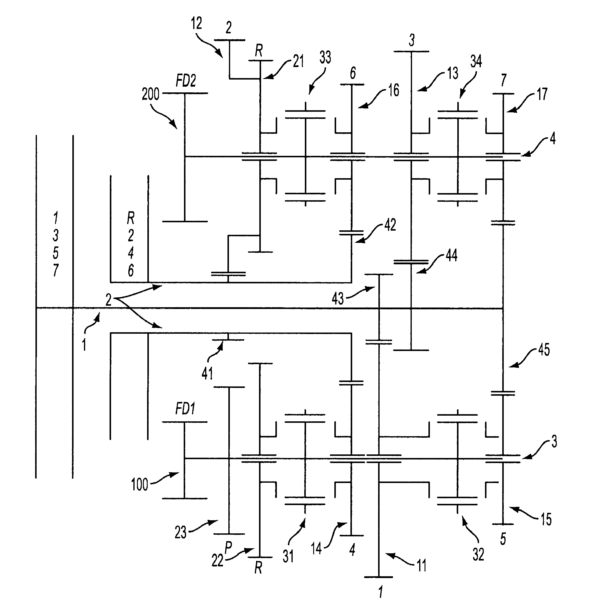
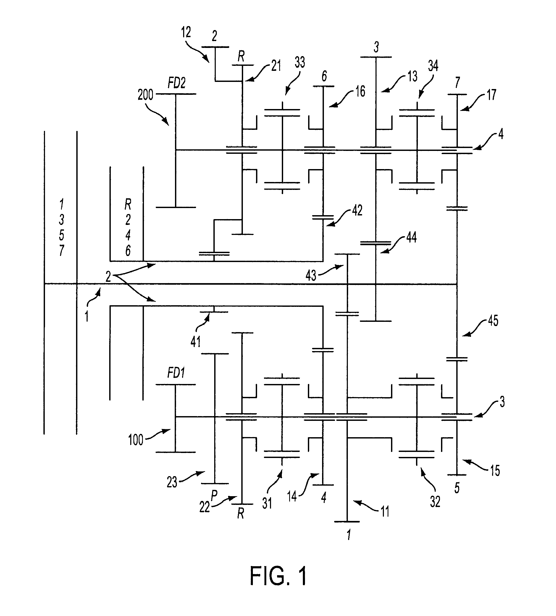
[0019]FIG. 1 illustrates a stick drawing of a transmission having a first dual use mesh for the fourth driven gear 14 and the sixth driven gear 16 and a second dual use mesh for the fifth driven gear 15 and seventh driven gear 17 according to an embodiment disclosed herein. The transmission includes a first input shaft 1 and a concentric second input shaft 2 which surrounds at least a portion of the first input shaft 1. The first input shaft 1 includes a plurality of fixedly attached gears 43, 44, 45. The gears 43, 44, 45 fixedly attached to the first input shaft 1 include a first driver gear 43, a third driver gear 44, and a fifth / s...


PUM


Abstract

A dual mesh gear system is provided for a motor vehicle transmission having three axes. The transmission includes two input shafts, first and second clutch assemblies, first and second countershafts, and an output shaft. The transmission uses a first dual mesh for gears four and six and a second dual mesh for gears five and seven. Reverse within the transmission is driven by a reverse driver gear fixedly attached to second gear on the second countershaft. The reverse driver gear is continuously meshed with a reverse driven gear on the first countershaft. The reverse gear combination achieves a reverse gear ratio greater than or equal to the gear ratio of first gear.

Description

FIELD OF THE INVENTION[0001]Embodiments disclosed herein relate generally to a transmission for a motor vehicle, and more particularly, to a 7-speed layshaft geartrain with dual-use meshes and three axes.BACKGROUND OF THE INVENTION[0002]A transmission is typically employed in motor vehicles to transfer power from a propulsion source to driven wheels. A typical propulsion source, such as an internal combustion engine, has a limited range of rotational speeds. Thus, the transmission typically is provided with a means to vary the ratio between the rotational velocity of the propulsion source and the rotational velocity of the driven wheels. Transmissions typically have a plurality of fixed ratios by which the rotational velocity of the propulsion source corresponds to the rotational velocity of the driven wheels.[0003]Typical transmissions employ a clutch mechanism and two shafts. The clutch mechanism interrupts the power transfer between the engine and the transmission by interrupting...

Claims


Application Information

Patent Timeline
Patent Type & Authority Applications(United States)
IPC IPC(8): F16H37/06F16H1/22
CPCF16H3/006F16H2003/0822Y10T74/19121F16H2003/0931F16H2200/0056F16H2003/0826
Inventor SILVA, LEE T.MARTIN, BERTHOLD
Owner FCA US
Why Eureka
Try Eureka