Regulated Descender

a descender and regulated technology, applied in the field of ascenders, can solve the problems of inertia becoming a significant factor, the jump does not achieve the desired effect of free fall, and the spool is relatively slow to accelera

Inactive Publication Date: 2011-06-23
DROP ZONE UK
View PDF25 Cites 2 Cited by
  • Summary
  • Abstract
  • Description
  • Claims
  • Application Information

AI Technical Summary

Benefits of technology

[0020]To prevent the descent from going astray, for instance because of winds, the harness of the descender

Problems solved by technology

We have found, however, that for large descents (say ˜100 m) the size of spool needed to accommodate the line is such that its inertia becomes a significant factor.
Thus, even when the apparatus is arranged s

Method used


Image

  • Regulated Descender
  • Regulated Descender
  • Regulated Descender

Examples


Embodiment Construction

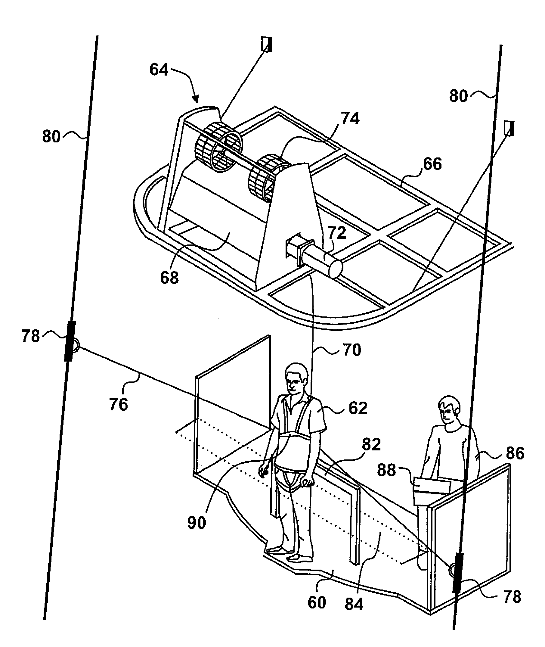
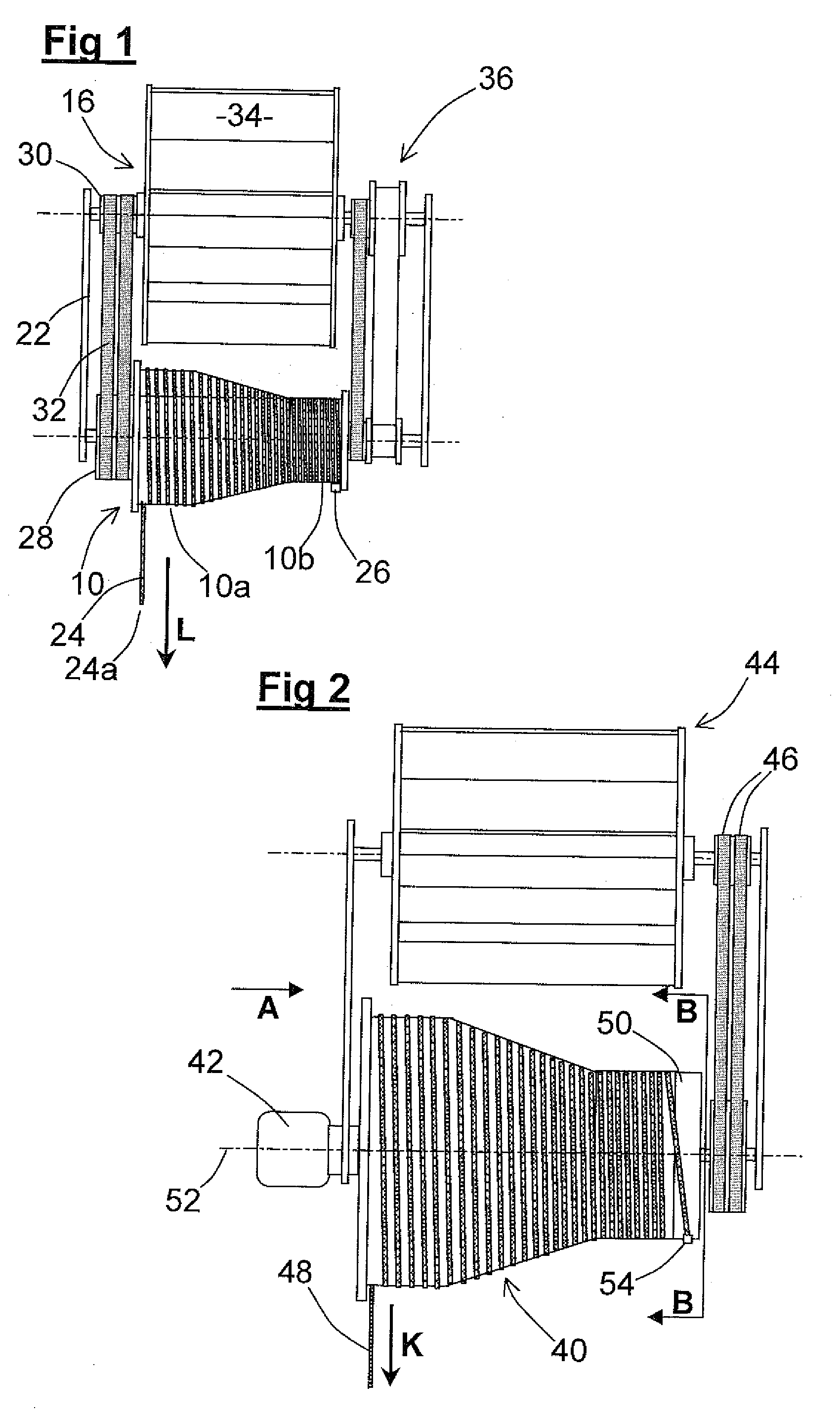
[0032]Referring first to FIG. 1, the regulating apparatus shown therein is of the kind described in our copending patent application EP 1996296. This regulating apparatus comprises a spool 10 mounted on a spindle 12 to be rotatable about a first axis 14 and a fan 16 mounted on a spindle 18 to be rotatable about a second axis 20 parallel to the first axis 14. The spindles 12 and 18 extend between a pair of end plates 22 thereby forming a frame for the regulating apparatus. A line 24 having a free end 24a is wound helically upon the spool 10, its other end being secured to the spool 10 by a clamp 26. The line 24 is a braid of gel-spun polyethylene filaments with high strength, high modulus and low creep available under the registered trade mark Dyneema from DSM of The Netherlands.

[0033]Secured to one end (the left hand end as seen in FIG. 1) of the spool 10 and rotatable about the spindle 12 is a first drive pulley 28. Secured to the left hand end of the fan 16 and rotatable therewith...


PUM


Abstract

Regulating apparatus for a descender comprises a spool 40, a line 48 wound upon the spool 40 to be drawn off during a descent and a fan 44 or similar brake operative upon the spool to limit its speed of forward rotation and hence the rate of descent. The inertial retarding effect of the moment of inertia of the spool 40 is overcome by an electric motor 42 arranged to accelerate the spool 40 during an initial part of the descent. A free-wheeling tether 50 for the line 48 prevents overrun of the spool 40 from picking up the line 48 at the end of a descent. The motor 42 may be run in reverse to rewind the line 48 after a descent.

Description

CROSS-REFERENCE TO RELATED APPLICATIONS[0001]This application claims priority from United Kingdom Patent Application No. 09 10 998.4, filed Jun. 24, 2009, and also from United Kingdom Patent Application No. 10 04 867.6, filed Mar. 24, 2010, the whole contents of which are incorporated herein by reference in their entirety.BACKGROUND OF THE INVENTION[0002]This invention concerns a descender regulated to control descent from a height.[0003]A descender is a facility for recreational, educational, training or safety purposes. It comprises an elevated platform (which may form part of or be set upon a tower, a bridge, a crane cradle, a building or a tree etc) from which a user jumps, his fall being controlled by a brake operating on a line connected to the jumper by means of a harness. Typically the line is wound on a spool connected to a fan so that as the jumper descends the fan is rotated and the windage of the fan controls the rate of descent. We describe such an arrangement in our co...

Claims


Application Information

Patent Timeline
IPC IPC(8): A62B1/08
CPCB64D23/00A62B1/12A62B1/06
Inventor MORIARTY, NICHOLASSHAYLOR, MATTHEW JOHN
Owner DROP ZONE UK
Why Eureka
Try Eureka