Spherical light output LED lens and heat sink stem system
What is Al technical title?
Al technical title is built by PatSnap Al team. It summarizes the technical point description of the patent document.
a technology of led lenses and stems, applied in semiconductor devices, lighting and heating apparatus, instruments, etc., can solve problems such as color shift, reduced light output, and shortened li
Active Publication Date: 2011-06-23
BHAIRI MALEK
View PDF73 Cites 32 Cited by
Summary
Abstract
Description
Claims
Application Information
AI Technical Summary
This helps you quickly interpret patents by identifying the three key elements:
Problems solved by technology
Method used
Benefits of technology
[0036]FIG. 10 features an LED device package of FIG. 5 adopted for use in a conventional incandescent Edison bulb package.
[0037]FIG. 11 fea
Problems solved by technology
Increased Junction temperature; heat that builds up inside the LED device, will lead to color shift, reduced light output, shortened life and ultimately device failure.
In addition, drive current, thermal path and ambient temperature also affects the junction temperature.
Furthermore, high-flux LEDs, which are needed for conventional light illumination, require higher drive c
Method used
Image
Click on the blue label to locate the original text in one second.
Reading with bidirectional positioning of images and text.
Examples
Embodiment Construction
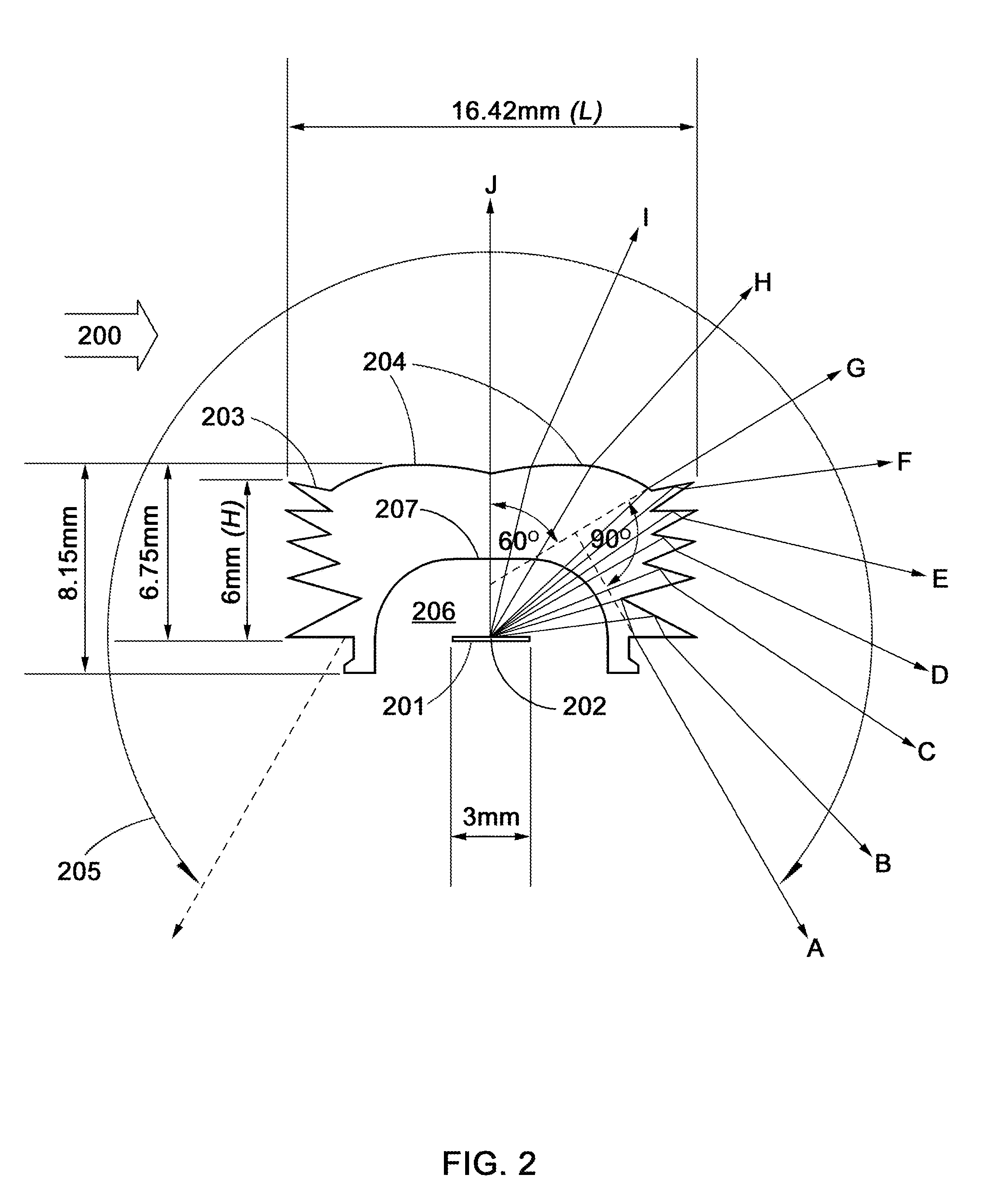
[0038]FIG. 2 illustrates an example of a spherical light producing lens in accordance with one embodiment of the invention. Light rays A through G emanating from an LED die 201, with a focal point 202, are totally internally reflected then refracted out of the lens 200 by the pointed elements 203 through a 90 degree angle. The top surface of the pointed elements 203 may be coated with a reflective material such as aluminum (AL) or nickel chrome (NiCr). Light rays G through J are refracted out of the double crown lens portion 204 through a 60 degree angle. Collectively, all the light rays emitted by the LED die 201 radiate around a 300 degree lighting angle 205 in the vertical plane and a 360 degree lighting angle in the horizontal plane. Surface 207 may be shaped to direct more light rays emitted from the LED die 201 towards a particular section of the lens, such as the pointed elements 203.
[0039]The length of the die 201 is directly proportional to the size of the lens 200. The len...
PUM
Abstract
This light emitting LED device provides a 360 degree lighting angle in the horizontal plane and a 300 degree lighting angle in the vertical plane while simultaneously addressing LED die thermal management; critical to high lumen output LEDs.
This LED lighting device is comprised of the LED lens, the LED holder and the heat sink stem.
Light produced by at least one LED die traveling vertically is diffused by the top refractive portion of the lens. Light rays directed towards the pointed elements are totally internally reflected downwards then refracted out of the lens, thus resulting in a spherical light pattern.
This technology is designed as a replacement for conventional light sources, such as; incandescent light bulbs, halogen bulbs, CFLs (compact fluorescent lamps) and metal halide lamps.
Application Information
Patent Timeline
Application Date:The date an application was filed.
Publication Date:The date a patent or application was officially published.
First Publication Date:The earliest publication date of a patent with the same application number.
Issue Date:Publication date of the patent grant document.
PCT Entry Date:The Entry date of PCT National Phase.
Estimated Expiry Date:The statutory expiry date of a patent right according to the Patent Law, and it is the longest term of protection that the patent right can achieve without the termination of the patent right due to other reasons(Term extension factor has been taken into account ).
Invalid Date:Actual expiry date is based on effective date or publication date of legal transaction data of invalid patent.