
Dynamic range improvements of load modulated amplifiers

a load modulation and amplifier technology, applied in the direction of amplifier combinations, amplifiers, electrical apparatus, etc., can solve the problems of high linearity, leakage of interfering signal energy between channels, distortion within each channel, etc., and achieve the effect of high power efficiency

Inactive Publication Date: 2011-06-23
TELEFON AB LM ERICSSON (PUBL)
View PDF7 Cites 32 Cited by
  • Summary
  • Abstract
  • Description
  • Claims
  • Application Information

AI Technical Summary

Benefits of technology

[0029]This is a technique suitable for amplifiers that work poorly when the input signal is backed off like the Current mode Class D, Class B, Class C, Class D, Class E, Class E / F and Class F amplifiers. For example by using load modulation in combination with outphasing and EER, the efficiency can be maintained over the output power range where the impedance tuner can track the optimum impedance for the amplifier at each power level. Outside the tunable area the efficiency drops quickly but the dynamic range of the system is increased so that highly dynamic signals like the UMTS signals still can be amplified linearly into the load.

Problems solved by technology

High linearity is required since nonlinear amplifiers would cause leakage of interfering signal energy between channels and distortion within each channel.
Various attempts have been made to address this problem, however it remains difficult to design a high efficiency power amplifier system that is at the same time also able to linearly amplify wide bandwidth signals.
Signal combining networks are not trivial to implement and it is especially complicated to attain the desired operation of the amplifier system when utilizing Chireix networks.
Further, the efficiency of Chireix is sensitive for parasitic disturbances and decreases rapidly due to parasitic components in the transistors of the system.
A common problem for the above listed systems and methods is their limited capability to linearly amplify wide bandwidth signals.

Method used


Image

  • Dynamic range improvements of load modulated amplifiers
  • Dynamic range improvements of load modulated amplifiers
  • Dynamic range improvements of load modulated amplifiers

Examples


Embodiment Construction

[0044]The present invention will be described more fully hereinafter with reference to the accompanying drawings, in which preferred embodiments of the invention are shown. This invention may, however, be embodied in many different forms and should not be construed as limited to the embodiments set forth herein: rather, these embodiments are provided so that this disclosure will be thorough and complete, and will fully convey the scope of the invention to those skilled in the art.

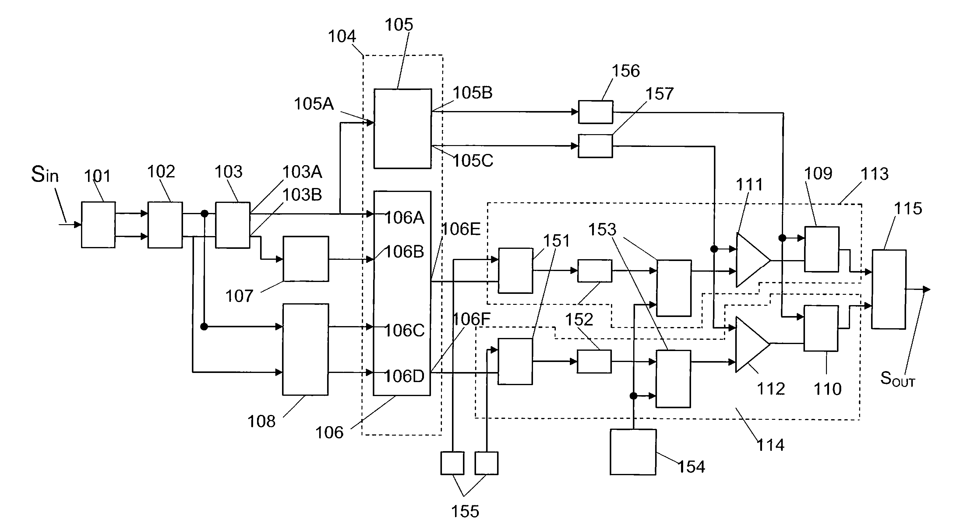
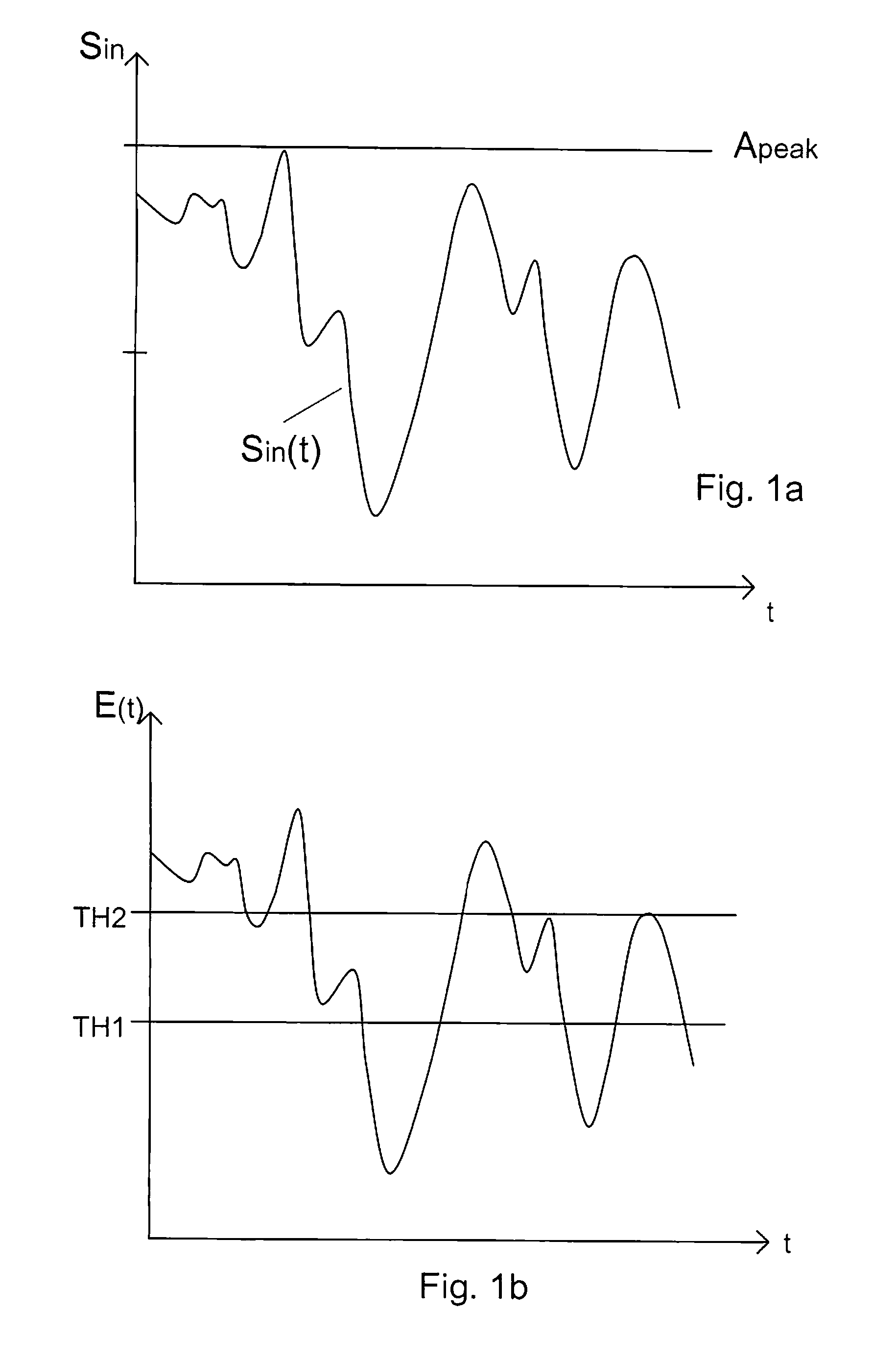
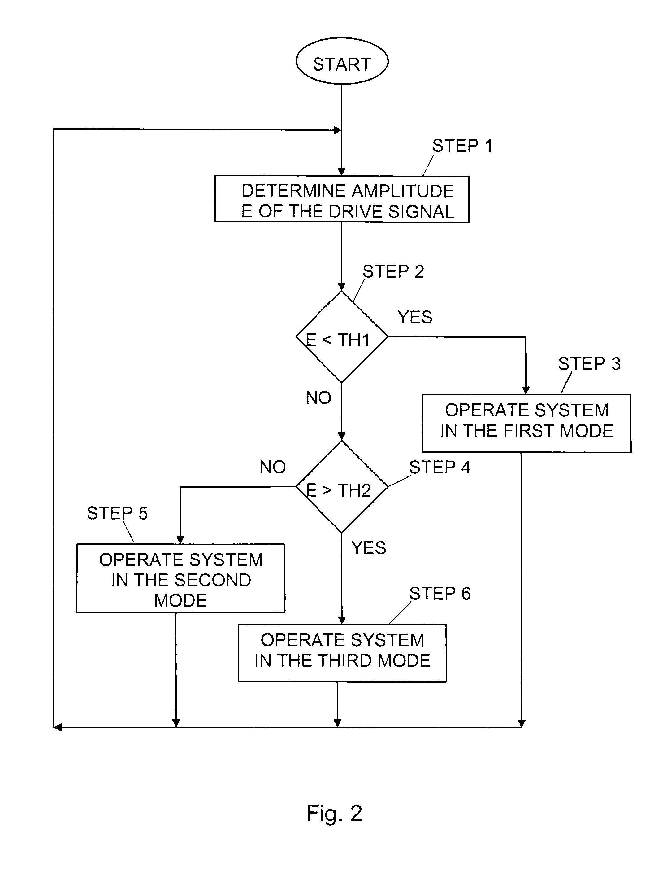
[0045]In FIG. 1a is a possible variation over time of an input signal, drive signal, Sin(t) to a power amplification system according to the present invention illustrated. One idea according to the present invention is to control the functionality of a power amplifier system capable of operating in at least three different amplification modes. For this purpose, an envelope signal is determined. The envelope E of the drive signal controls an integrated switch network that routes both the signal envelope and ...


PUM


Abstract

The present invention relates to methods and devices to control and operate the functionality of a power amplifier system (100) capable of operating in at least three differential amplification modes. The drive signal's amplitude envelope controls an integrated switch network (104; 105, 106) that routes both the signal envelope and signal phase to different modulation blocks (111, 112: 109, 110: 115). Depending on the envelope strength, the operational mode of the amplifier system is possible to alter to best serve the signal statistics to provide the highest overall power efficiency.

Description

TECHNICAL FIELD OF THE INVENTION[0001]The present invention relates generally to power amplifiers and amplifying methods, and more specifically to high efficiency power amplifiers.DESCRIPTION OF RELATED ART[0002]In radio transmitters for broadcast, cellular and satellite systems the power amplifier in the transmitter has to be very linear in addition to being able to simultaneously amplify many radio channels (i.e. frequencies) spread across a wide bandwidth. High linearity is required since nonlinear amplifiers would cause leakage of interfering signal energy between channels and distortion within each channel.[0003]In the wireless communication industry, a premium is placed on the ability to amplify wide bandwidth signals. e.g. spread spectrum signals, in highly efficient manner. To limit the size of the DC power supply and cooling equipment in a radio base station, it is essential to keep a high overall power efficiency. Various attempts have been made to address this problem, ho...

Claims


Application Information

Patent Timeline
IPC IPC(8): H03F3/68
CPCH03F1/0205H03F1/0266H03F1/0294H03F1/3294H03G3/3042H03F3/24H03F2200/102H03F2200/252H03F2200/336H03F3/19
Inventor LEJON, THOMASREXBERG, LEONARD
Owner TELEFON AB LM ERICSSON (PUBL)
Learn More