Image display device, image display viewing system and image display method
a technology of image display and viewing system, applied in the direction of color television details, instruments, electrical devices, etc., can solve the problems of significant cost increase, two images before and after rewriting look as if, and significant cost increase becomes inevitable, so as to prevent a plurality of periodically displayed images and simple structure
Inactive Publication Date: 2011-06-23
SATURN LICENSING LLC
View PDF11 Cites 25 Cited by
- Summary
- Abstract
- Description
- Claims
- Application Information
AI Technical Summary
Benefits of technology
[0010]In light of the foregoing, it is desirable to provide a novel and improved image display device, image display viewing system and image display method that are capable of reliably preventing a plurality of periodically displayed images from being visually perceived in a mixed manner, while maintaining a simple structure.
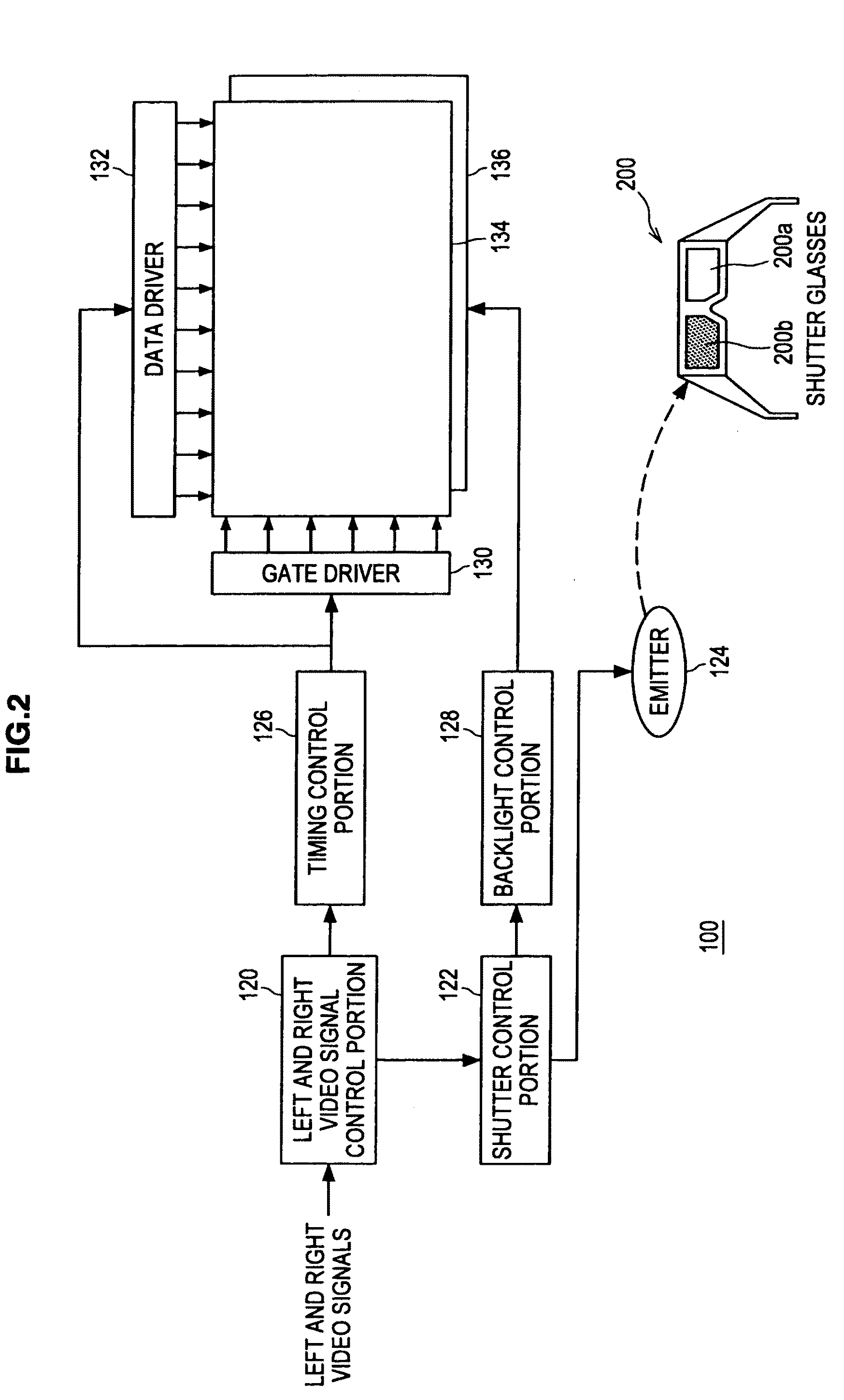
[0019]According to another embodiment of the present invention, there is provided an image display method, comprising the steps of displaying a plurality of different images periodically, generating timing signals for driving shutters for a right eye and a left eye, in synchronization with the periodical display of a display panel, with respect to glasses for viewing images, the glasses being provided with the shutters for the right eye and the left eye, and causing respective light sources that are provided on two opposing side faces of a light guide plate of a backlight to blink at different timings during an opening period of the shutters, the backlight being provided with the light guide plate with a size corresponding to a display area of the display panel and the light sources that are provided on the two opposing side faces of the light guide plate.
[0020]According to the embodiments of the present invention described above, it is possible to reliably prevent a plurality of periodically displayed images from being visually perceived in a mixed manner, while maintaining a simple structure.
Problems solved by technology
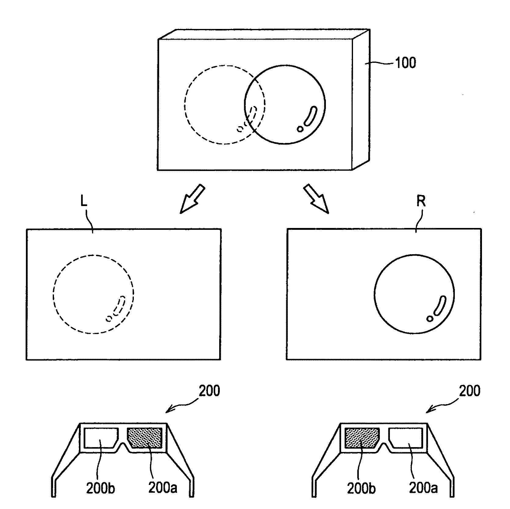
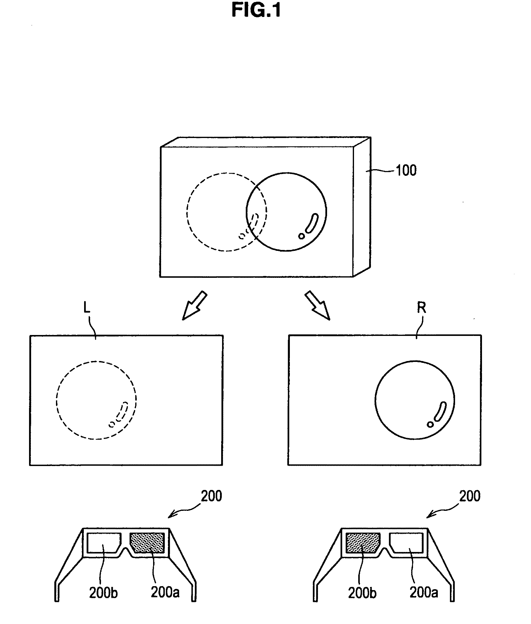
Incidentally, in the case of a hold-type display device such as a liquid crystal display, since a screen is normally rewritten sequentially from an upper section of the screen, when the shutters provided in a pair of glasses open while scanning is performed within the screen, a problem arises in which two images before and after the rewriting look as if they are overlapped.
As a result, the shutters open in a state in which a previous screen still remains, and a problem arises in which right and left images are displayed in a mixed manner particularly in the lower section of the screen.
However, in this case, it is necessary to operate the liquid crystal display twice as fast as normal, and a significant cost increase becomes inevitable, due to, for example, an increase in frame memory etc.
Method used
View moreImage
Smart ImageViewing Examples

Examples
second embodiment (
2. Second Embodiment (Configuration Example of Reducing Effects Caused by Delay in Response of Shutters)
third embodiment (
3. Third Embodiment (Example of Scan Lighting of Backlight)
fourth embodiment (
4. Fourth Embodiment (Application to System that Periodically Displays a Plurality of Different Images)
Login to View More PUM
 Abstract
An image display device includes a display panel that periodically displays different images, a shutter control portion that generates timing signals for driving shutters for a right eye and a left eye, in synchronization with the periodical display of the display panel, with respect to glasses for viewing images, the glasses being provided with the shutters for the right and left eye, a backlight that includes a light guide plate of a size corresponding to a display area of the display panel and light sources that are provided on two opposing side faces of the light guide plate and that irradiates the display panel from a rear side of the display panel, and a backlight control portion that causes the respective light sources that are provided on the two opposing side faces to blink at different timings during an opening period of the shutters.
Description
CROSS-REFERENCE TO RELATED APPLICATION[0001]The present application claims priority from Japanese Patent Application No. JP 2009-289463 filed in the Japanese Patent Office on Dec. 21, 2009, the entire content of which is incorporated herein by reference.BACKGROUND OF THE INVENTION[0002]1. Field of the Invention[0003]The present invention relates to an image display device, an image display viewing system and an image display method.[0004]2. Description of the Related Art[0005]Recently, a technology such as that described in Japanese Patent No. 3701355, for example, has become known that displays a plurality of video images on a single screen in a time-division manner and that uses a pair of glasses with shutters that are synchronized to the timing of the displayed images in order to separate the plurality of the video images and recognize them individually. A technology such as that described in Japanese Patent Application Publication No. JP-A-61-227498 is also known that makes it p...
Claims
Login to View More Application Information
Patent Timeline
 Patent Type & Authority Applications(United States)
IPC IPC(8): H04N13/04
CPCG09G3/003H04N13/0497G09G3/342G09G3/3648G09G2320/0242G09G2310/024G09G2310/08G02B27/2264H04N13/0438G02B30/24H04N13/341H04N13/398
Inventor ITO, ATSUSHIODA, KYOICHIRO
Owner SATURN LICENSING LLC
Features
- R&D
- Intellectual Property
- Life Sciences
- Materials
- Tech Scout
- Unparalleled Data Quality
- Higher Quality Content
- 60% Fewer Hallucinations
Learn More Browse by: Latest US Patents, China's latest patents, Technical Efficacy Thesaurus, Application Domain, Technology Topic, Popular Technical Reports.
© 2025 PatSnap. All rights reserved.Legal|Privacy policy|Modern Slavery Act Transparency Statement|Sitemap|About US| Contact US: help@patsnap.com