
Electronic device carrier

a technology of applied in the direction of electric apparatus casings/cabinets/drawers, instruments, furniture parts, etc., can solve the problems of excessive friction between electronic devices and carriers, damage to the edges of electronic devices or a corresponding portion of the electronic device, etc., to achieve smooth removal or positioning, efficient reduction of friction between electronic devices

Inactive Publication Date: 2011-06-23
ASKEY COMP
View PDF12 Cites 1 Cited by
  • Summary
  • Abstract
  • Description
  • Claims
  • Application Information

AI Technical Summary

Benefits of technology

[0007]It is an objective of the present invention to provide an electronic device carrier comprising a rolling element for rolling and thereby having point contact with an electronic device so as to efficiently reduce friction between the electronic device and a base of the electronic device carrier, so as to allow the electronic device to be smoothly removed or positioned, and it protects the electronic device and the base from damage.
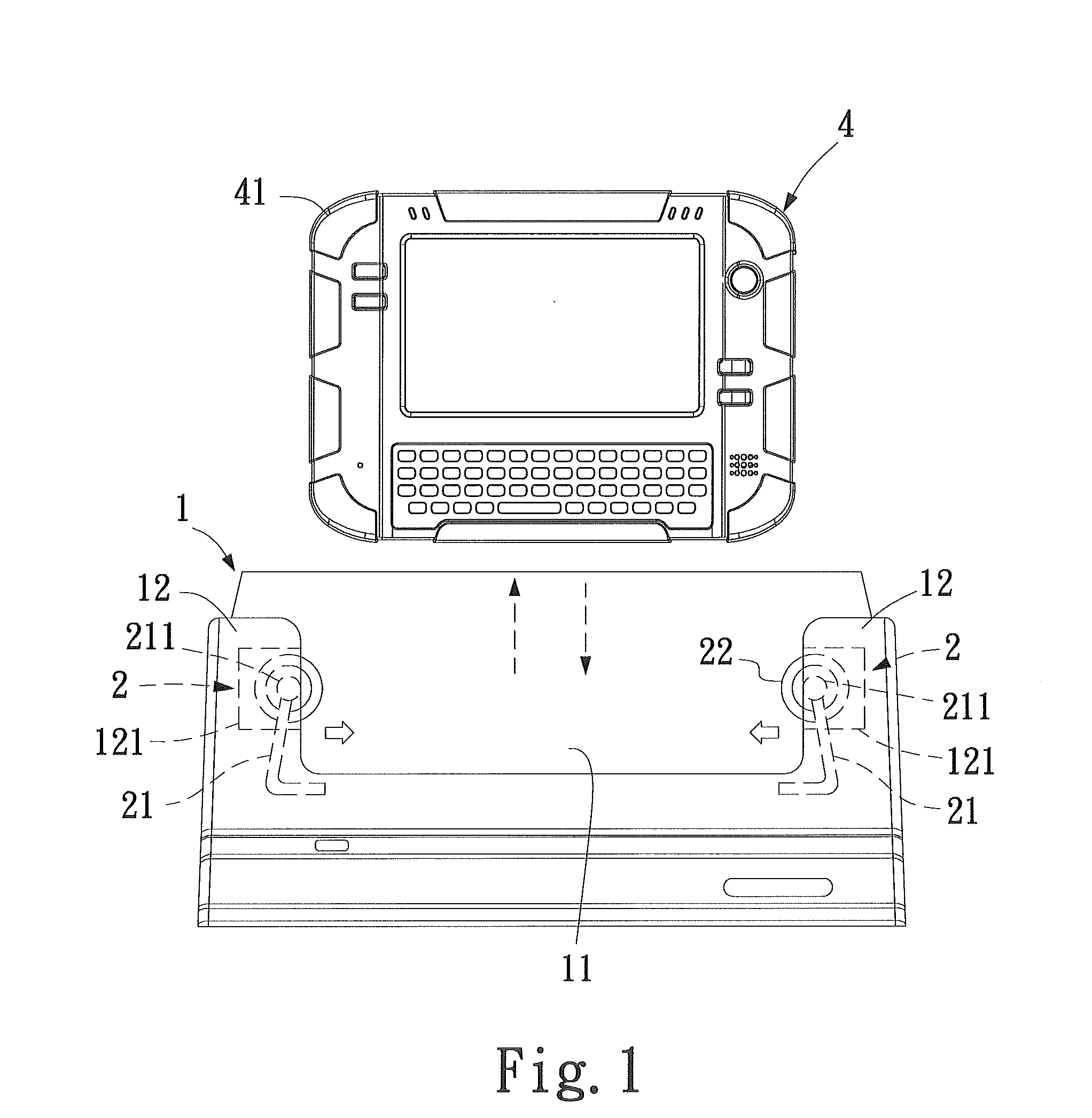
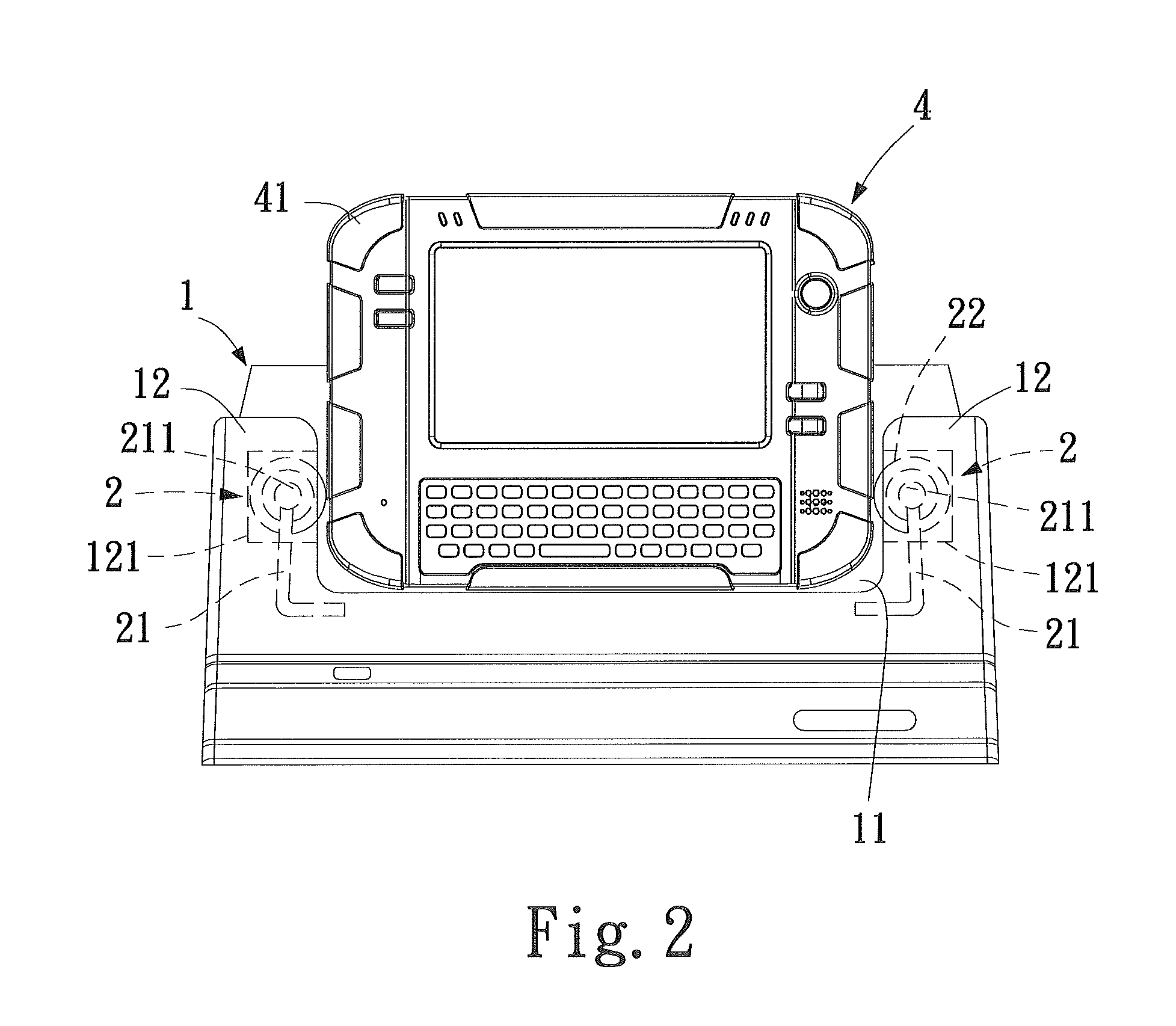
[0012]When the electronic device is positioned in the receiving chamber of the base or removed from the receiving chamber of the base, the electronic device comes into contact with the rolling element of the rolling devices. Consequently, the rolling movement of the rolling element provides the point contact between the rolling element and the electronic device, thus the friction between the electronic device and the base is effectively reduced. As a result, the removal and positioning of the electronic device is smooth, and the electronic device or the base is protected from damage.

Problems solved by technology

In so doing, friction arises between the electronic device and the carrier while the electronic device is being removed from or placed on the carrier.
In this regard, rubber is notorious known for its excessive friction, which not only prevents the conventional electronic device from being smoothly removed from or positioned in the carrier but also damages the edges of the electronic device or a corresponding portion of the carrier.
However, the wearproof base structure cannot reduce friction at all.
However, the recharger structure is not free from the excessive friction while being removed or positioned.
However, great friction is generated between the mobile phone and the clamping mechanisms in the course of the removal or the positioning of the mobile phone.

Method used


Image

  • Electronic device carrier
  • Electronic device carrier
  • Electronic device carrier

Examples


Embodiment Construction

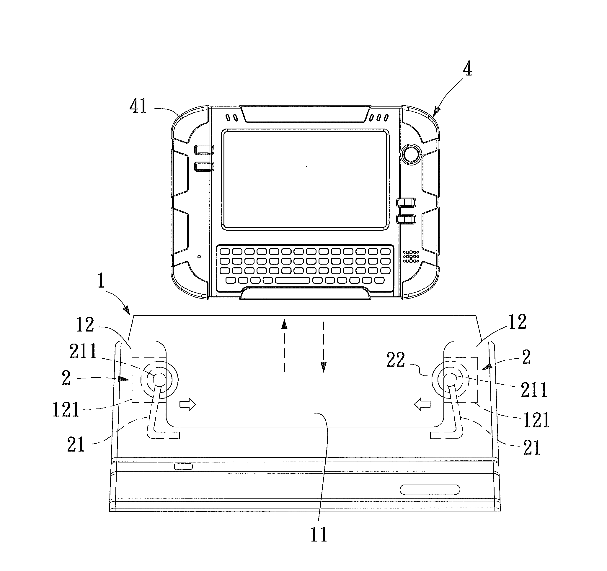
[0027]Referring to FIG. 1 through FIG. 9, in an embodiment of the present invention, an electronic device carrier is configured to carry an electronic device 4 having two opposing sides. The electronic device carrier comprises a base 1 and two rolling devices 2. The base 1 has a receiving chamber 11 for receiving the electronic device 4. The two rolling devices 2 are provided at two sidewalls 12 of the two ends of the receiving chamber 11 respectively, and are utilized for rotational contact with the sides of the electronic device 4. The base 1 is concavely provided with the receiving chamber 11 and has two sidewalls 12 positioned at the two opposing ends of the receiving chamber 11, respectively. Each of two said sidewalls 12 is concavely provided with a chamber opening 121 facing to the receiving chamber 11. Each of two rolling devices 2 comprises a resilient element 21 and a rolling element 22. The resilient element 21 of each of the rolling devices 2 is coupled to the base 1 and...


PUM


Abstract

An electronic device carrier comprising a base and rolling devices. When an electronic device is removed from a receiving chamber of the base, the rolling devices can reduce friction effectively and resilient force of the rolling device can fix the electronic device in the receiving chamber. The electronic device carrier further includes a transmission unit for transmitting data whenever the electronic device is positioned in the receiving chamber.

Description

CROSS-REFERENCE TO RELATED APPLICATIONS[0001]This non-provisional application claims priority under 35 U.S.C. §119(a) on Patent Application No(s). 098143445 filed in Taiwan, R.O.C. on 17 Dec. 2009, the entire contents of which are hereby incorporated by reference.FIELD OF THE INVENTION[0002]The present invention relates to electronic device carriers, and more particularly, to an electronic device carrier that can be removed without producing much fiction and can position the electron device at its location firmly.BACKGROUND OF THE INVENTION[0003]A conventional electronic device is usually placed on a carrier or usually requires a carrier, for recharging or data transmission purpose. In so doing, friction arises between the electronic device and the carrier while the electronic device is being removed from or placed on the carrier. Plenty of the conventional electronic devices are encapsulated with the protective rubber. In this regard, rubber is notorious known for its excessive fri...

Claims


Application Information

Patent Timeline
Patent Type & Authority Applications(United States)
IPC IPC(8): H05K5/00B65D85/00
CPCG06F1/1626H04M1/04G06F1/1632H02J7/0044
Inventor HUANG, CHIH-HUACHANG, CHING-HUILEE, KO-HSIENHSIEH, CHING-FENG
Owner ASKEY COMP
Learn More