Adjustable Pocket Hole Apparatus

a pocket hole and adjustment technology, applied in the field of woodworking tools, can solve the problems of lack of flexibility of the current pocket hole machin

Inactive Publication Date: 2011-06-23
STUKULS ALFRED
View PDF18 Cites 21 Cited by
  • Summary
  • Abstract
  • Description
  • Claims
  • Application Information

AI Technical Summary

Benefits of technology

[0014]The spindle is mounted to a rail that is slidably mounted to the table so that the rail can slide perpendicularly to the drilling direction. The rail controls the perpend

Problems solved by technology

Current pocket hole machines su

Method used


Image

  • Adjustable Pocket Hole Apparatus
  • Adjustable Pocket Hole Apparatus
  • Adjustable Pocket Hole Apparatus

Examples


Embodiment Construction

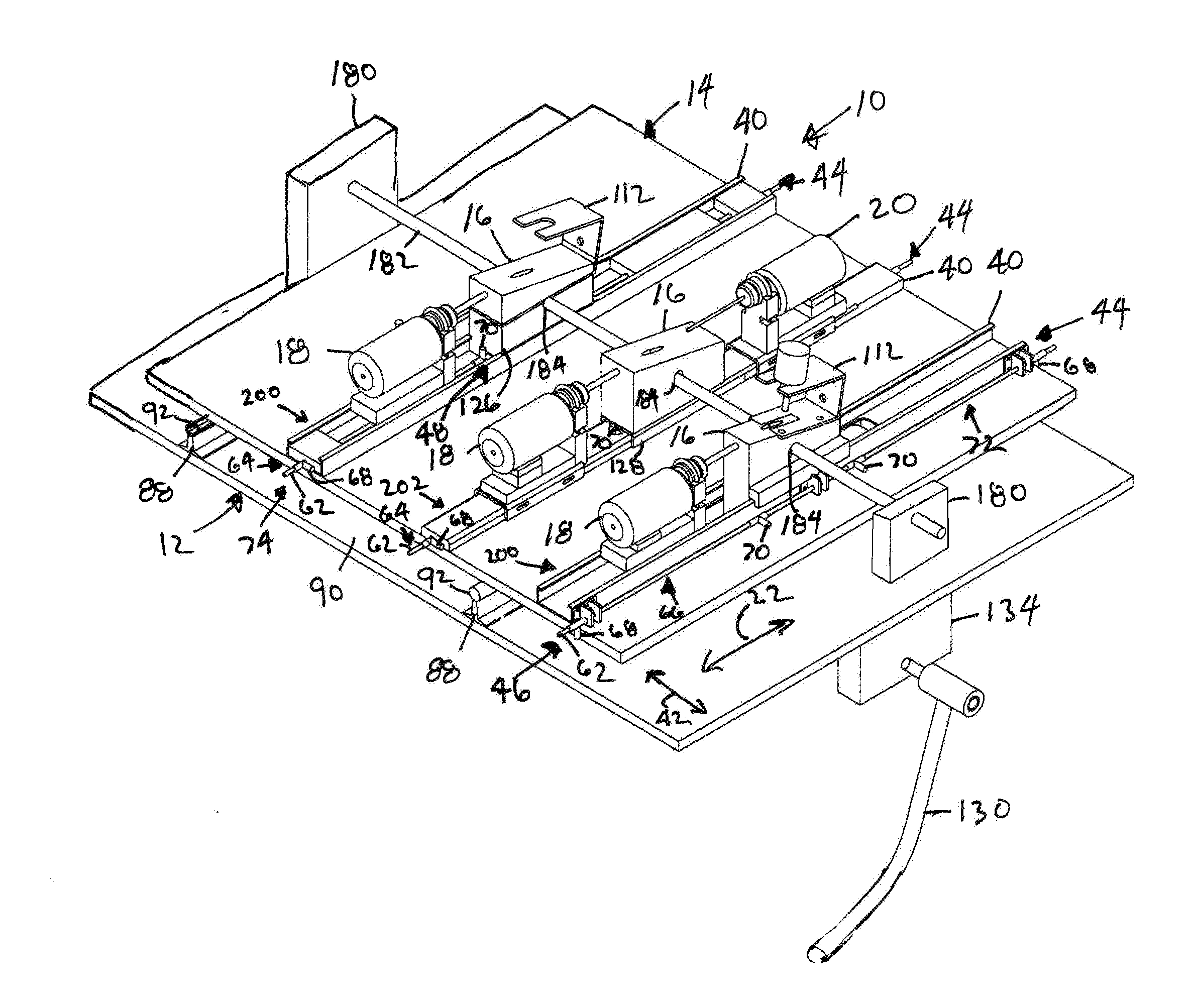
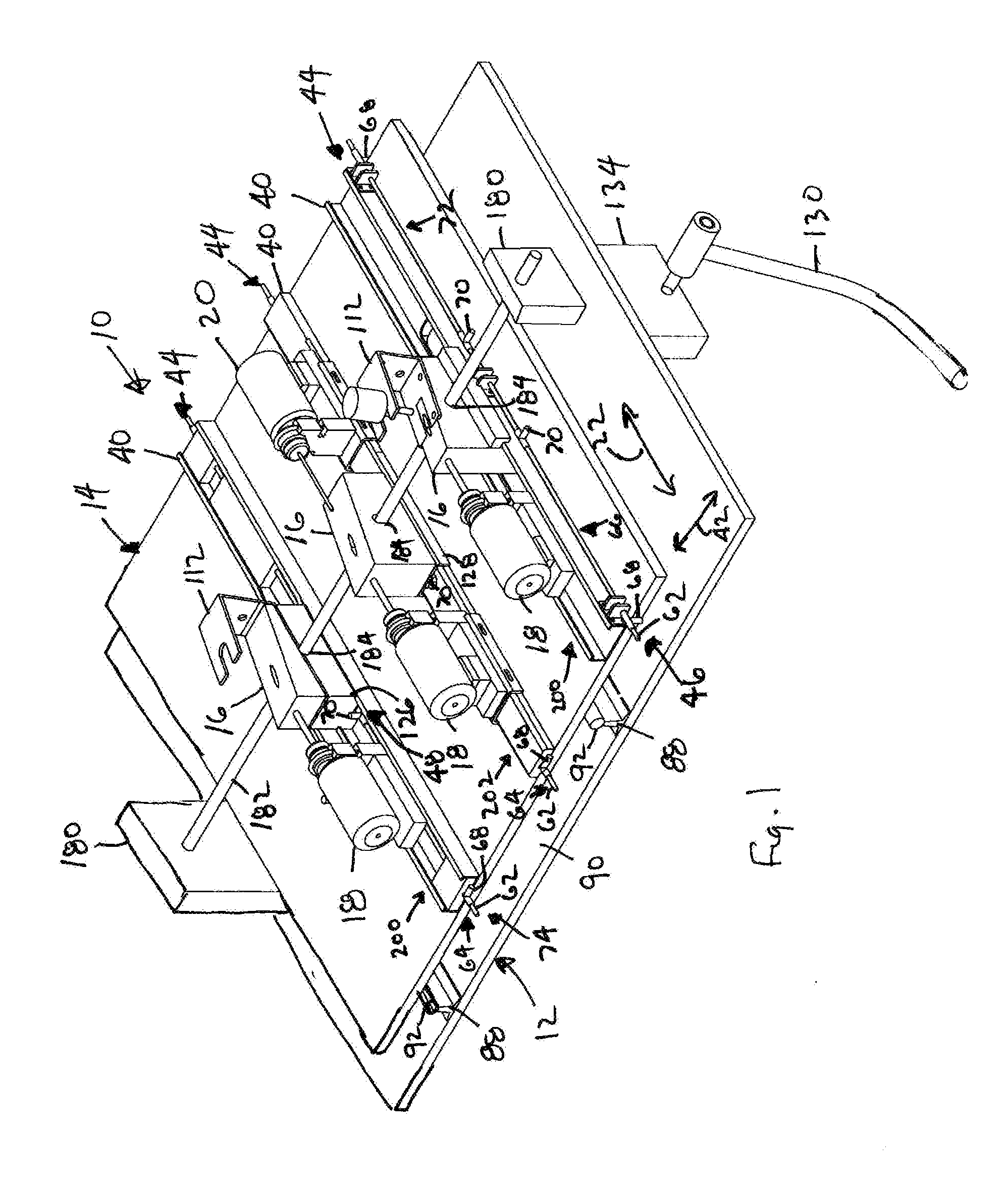
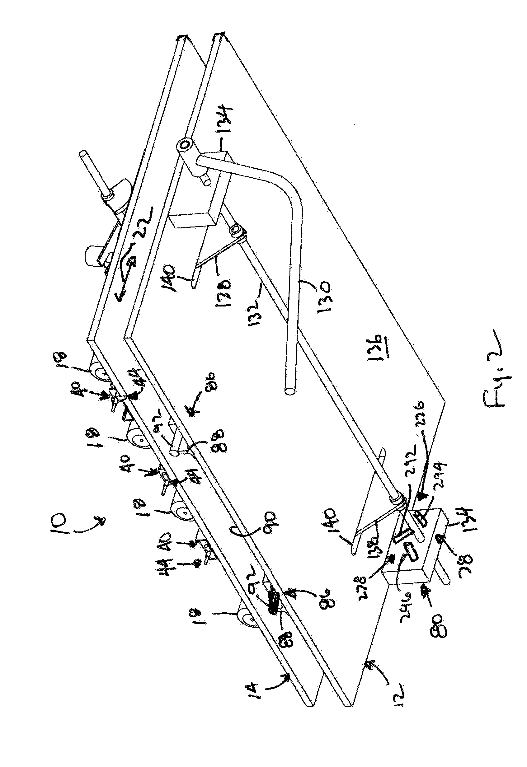
[0039]The present invention is a pocket hole machine (“PHM”) for drilling multiple pocket holes and where the spacing between holes is infinitely adjustable. The next paragraphs summarized the apparatus and the details follow.

[0040]The basic apparatus of the PHM of the present invention is shown in the figures. A table 14 reciprocates linearly relative to a base 12 in a drilling direction 22. An anvil 16 with a sloped top surface 102 is fixed relative to the base 12 in the drilling direction 22 and a drill spindle 18 with a step drill bit 30 is fixed relative to the table 14 in the drilling direction 22. The workpiece 2 is mounted to the anvil 16 while the table 14 is in a neutral position 24 shown in FIG. 22. The spindle 18 is started and the table 14 is moved in the drilling direction 22 from the neutral position 24 to the drill position 26 to drill the pocket hole 4. The table 14 is moved back to the neutral position 24 and the workpiece 2 is removed.

[0041]In order to allow for i...


PUM


Abstract

In the pocket hole apparatus of the present invention, a table reciprocates linearly relative to a base. An anvil is fixed relative to the base and holds the workpiece on a sloped top surface at the desired angle for the pocket hole. A drill spindle with a drill bit is fixed relative to the table. After the workpiece is mounted to the anvil, the table is moved to drill the pocket hole. Optionally, a second spindle on the opposite side of the anvil predrills the pocket hole when the table is first moved to a predrill position. The spindle is enabled or disabled by latching mechanism. The spindle is mounted to a rail that is slidably mounted to the table so that the rail can slide perpendicularly thereby adjusting the spacing between pocket holes.

Description

CROSS-REFERENCES TO RELATED APPLICATIONS[0001]Not ApplicableSTATEMENT REGARDING FEDERALLY SPONSORED RESEARCH OR DEVELOPMENT[0002]Not ApplicableREFERENCE TO A SEQUENCE LISTING, A TABLE, OR A COMPUTER PROGRAM LISTING COMPACT DISK APPENDIX[0003]Not ApplicableBACKGROUND OF THE INVENTION[0004]1. Field of the Invention[0005]The present invention relates to woodworking tools, more particularly, to an apparatus for drilling pocket holes.[0006]2. Description of the Related Art[0007]Pocket hole joinery involves drilling a hole at a shallow angle into one workpiece and then joining it to a second workpiece with a self-tapping screw. Pocket hole machines have at least one drill spindle mounted to a table or jig. The workpiece is mounted to the table at an angle to the spindle that matches the angle at which the hole is to be drilled. The spindle with a drill bit attached is pushed linearly to drill the hole.[0008]Current pocket hole machines suffer from a lack of flexibility. Most pocket hole m...

Claims


Application Information

Patent Timeline
IPC IPC(8): B23B41/00B23B47/28
CPCB23B39/161B27C3/04B27C3/06Y10T408/567Y10T408/385Y10T408/6786Y10T408/5612Y10T408/378Y10T408/3788Y10T408/3809Y10T408/5614Y10T408/6779Y10T408/3792Y10T408/5626B26F1/16B27G15/00
Inventor STUKULS, ALFRED
Owner STUKULS ALFRED
Why Eureka
Try Eureka